


Si85xx-TB UG
4 Confidential Rev. 0.1
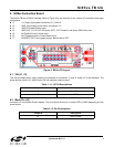
4.3. R1, R2, R3, R4 Inputs, OUT1, OUT2 Outputs (J4)
Connector J4 is used to provide the control inputs (R1, R2, R3, R4, MODE) to the Si85xx. It also provides the
output voltage of the sensed input current on OUT1 and OUT2.
4.4. IIN (J5)
Connector J5 is used to provide the positive current sense input to the Si85xx device.
4.5. IOUT (J6)
Connector J6 is used to provide the negative/return current sense input to the Si85xx device.
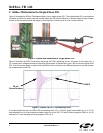
4.6. TRST RESET (J7)
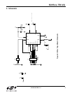
Connector J7 is used to set the timing for the Si85xx's integrator. J7 defaults to Reset option 1 where TRST is tied
VDD providing approximately 200 ns of reset time. Reset option 2 is selected by connecting a timing resistor (R1 in
Figure 4) from the TRST input to ground.
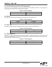
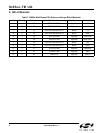
Table 3. J4 Pin Descriptions
Jumper # Description
J4 R1, R2, R3, R4, OUT1, OUT2, GND
Table 4. J5 Pin Descriptions
Jumper # Description
J5 IIN
Table 5. J6 Pin Descriptions
Jumper # Description
J6 IOUT
Table 6. J7 Pin Descriptions
Jumper # Description
J7 TRST – VDD or R1 to GND