


Si85xx-TB UG
2 Confidential Rev. 0.1
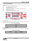
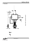
3. Si85xx-TB Hardwired to Single-Phase POL
Figure 2 illustrates the Si85xx-TB soldered directly into a single-phase POL. The single phase POL was designed
to operate at a 400 kHz switch rate and provide better than 90 percent efficiency. It also provides 10 amps of peak
current to the load and protects the supply by shutting down in the event of an over current condition.
Figure 2. Si85xx-EVB Hardwired to Single-phase POL
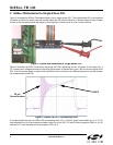
Figure 3 illustrates the Si8512 accurately monitoring the POL's switching current. As shown in the scope plot, a
1.6 V peak output voltage accurately monitors the 8 Amp peak, 50 percent duty cycle, 400 kHz current signal of the
POL. A 20 mΩ sense resistor in series with the Si85xx is also monitored via a differential probe to provide a base-
line measurement of the POL.
Figure 3. Si85xx-TB OUT1 Oscilloscope Plot
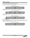
To accommodate this test, the Si85xx-TB was powered with a 5 V (100 mA) supply connected from J1 to J2. R1
was soldered from J4 to the respective phase control line of the POL. R2 and R4 were jumped to GND on J4. R3
was tied to 5 V and the Mode pin was jumped to VDD via J7.
Si8512
20 mΩ
Sense Resistor