


7
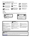
An Emission Control Label is located on the unit. (This is an EXAMPLE ONLY; information on label varies by en-
gine FAMILY).
PRODUCT EMISSION DURABILITY (EMISSION COMPLIANCE PERIOD)
The 300 hour emission compliance period is the time span selected by the manufacturer certifying the engine
emissions output meets applicable emissions regulations, provided that approved maintenance procedures are
followed as listed in the Maintenance Section of this manual.
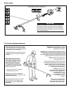
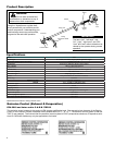
Assembly
This unit comes fully assembled with the exception of the cutting attachment
shield and cutting attachment.
Prior to Assembly
Before assembling, make sure you have all the components required for a
complete unit and inspect unit and components for any damage.
■ Engine and shaft assembly
■ Cutting attachment shield
■ Cutting attachment
■ Owner’s/operator’s manual
■ Assembly Tool (s)
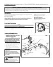
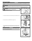
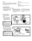
Cutting Attachment Shield
1. Insert the cutting attachment shield
between the outer tube and the cutting
attachment mounting plate.
CAUTION!
Make sure the clamp screw and
retaining nut are securely tightened
before tightening the four socket-head
cap screws.
NOTE:
It may be necessary to loosen the retain-
ing nut and clamp screw to adjust cutting
attachment shield mounting plate.
2. Fit the two shims and the bracket over
the outer tube and loosely install the
four socket-head screws.
3. Tighten the four socket-head cap
screws to secure the cutting attach-
ment shield.
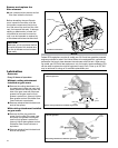
Outer Tube
Socket-Head
Cap Screws
Clamp Screw
Retaining
Nut
Drain
Screw
Mounting Plate
Shim
Shim
Bracket
Cutting
Attachment
Shield
Line Cutter
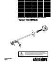
T282
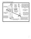
WARNING!
NEVER operate the unit
without the cutting attachment shield
installed and tightly secured!
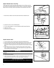
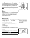
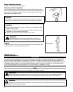
Front handle installation
NOTE:
Label shows minimum spacing for front handle location.
1. Position front handle for comfortable operation and secure screw.
Screw
Outer
Tube
Handle
Handle