


8
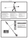
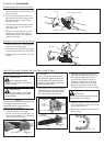
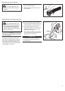
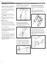
Tool assembly
Lower tube assembly
Coupler
Latch
Coupler screw
Knob
Locking hole
Latch protector (extended)
Assembly (continued)
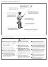
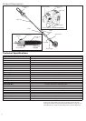
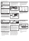
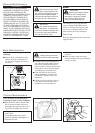
Adjusting the Throttle Cable
23145
Cable
Adjuster
Ignition
Leads
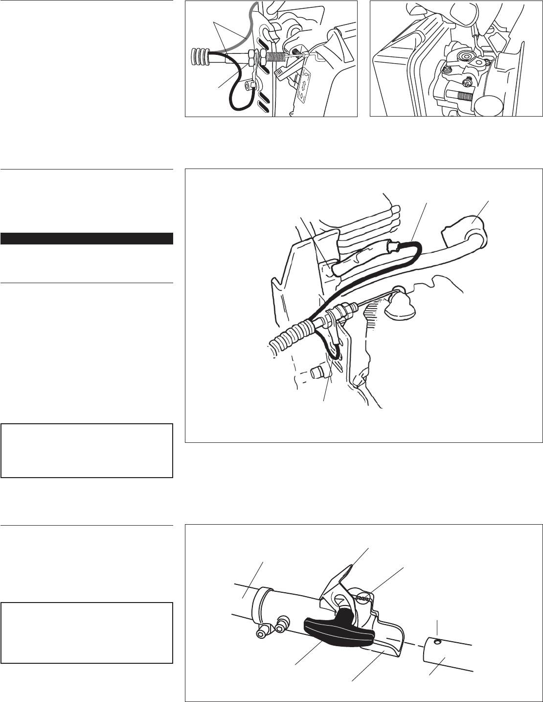
Connect The Throttle Cable
Loop the ribbed cable tube to the top
left side of the engine.
Install the black wire between the two
cable adjuster nuts as shown.
Connect the S-shaped end of the throt-
tle cable to the throttle lever on top of
the carburetor.
1.
2.
3.
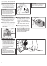
23146
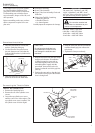
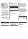
Insert the throttle cable housing into
the notch on the fan cover, and clamp
the black wire’s connector between the
fan cover and the cable outer adjuster
nut. See Figure 10.
1.
Spark plug
boot
Black wire
Ignition ground
lead (Black wire)
Tighten the two throttle cable adjuster
nuts.
Using finger pressure only, connect the
black switch wire from the cable tube to
the red ignition wire on the powerhead.
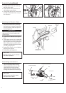
Wire routing must be as shown in the
illustration with the black wire located
over the spark plug wire..
Reinstall the cylinder cover and tighten
the three cover screws.
Reinstall the spark plug boot.
2.
3.
4.
5.
Red wire
IMPORTANT!
Adjust and tighten the cable nuts to allow
approximately 1/4-inch freeplay at the
throttle trigger.
CAUTION!
Routing of wiring must not interfere
with throttle operation.
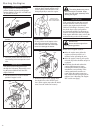
Assembling tube sections
Place powerhead/lower tube assem-
bly on a clean, flat surface so that
both assemblies fit end to end. The
powerhead/lower tube assembly
should be facing positioned with the
locking hole in the tube end facing up.
1.
CAUTION!
Keep the open ends of the tubes
clean and free of debris!