


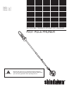
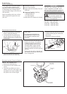
Tube Clamp
Hex
Wrench
7
IMPORTANT!
The terms “left”, “left-hand”, and “LH”;
“right”, “right-hand”, and “RH”; “front”
and “rear” refer to directions as viewed by
the operator during normal operation.
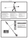
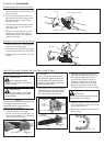
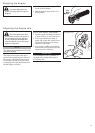
Using Figure above as a guide, familiar-
ize yourself with the Shindaiwa P231
pole pruner and its various components.
Understanding your unit helps ensure
top performance, longer service life, and
safer operation.
Before assembling, make sure you have
all the components required for a com-
plete unit:
WARNING!
Do not make unauthorized
modications or alterations to your
pruner or its components.
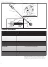
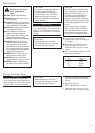
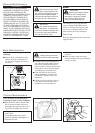
Bar and Chain Options
8 inch Bar
—
90SG-33E Chain
10 inch Bar
—
90SG-39E Chain
12 inch Bar
—
90SG-44E Chain
CAUTION!
Do not force the shaft tube into
the powerhead! Excessive force
can damage the shaft tube and
mainshaft.
Add some moly-type EP grease to
splines at the end of the main shaft.
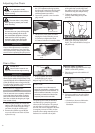
3.
Place the powerhead on a clean, flat
surface, spark plug facing up.
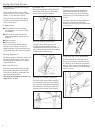
Use the 4mm hex wrench to loosen
the tube clamp screw. Verify that the
D-shaped shim washer is positioned as
shown below.
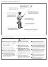
1.
2.
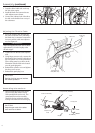
Slide the outer tube into the tube clamp
until the tube bottoms. If installation
is difficult, rotate the outer tube or
main shaft slightly until you feel the
mainshaft splines engage with the
powerhead. Outer tube needs to be
inserted so that the end of the grip hits
joint cap.
Position the outer tube so that the igni-
tion switch is facing up and the throttle
lever is facing down.
4.
5.
Powerhead Assembly
Lower Tube Assembly
Upper Tube/Saw Assembly, Chain and
Guide Bar
Chain CoverTool Kit Containing:
Spark Plug Wrench
4mm Hex Wrench
8 x 10mm Spanner
Carefully inspect all components for damage.
■
■
■
■
•
•
•
Powerhead Installation
Throttle Lever
Tube
Clamp
Grip
Clamp Screw
Main
Shaft
Ignition
Switch
Outer
Tube
Assembly
Slide the outer tube into the powerhead
until the throttle grip just contacts the
tube clamp.
Tighten the clamp screw firmly.
6.
7.
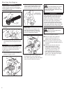
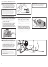
Prior to assembly
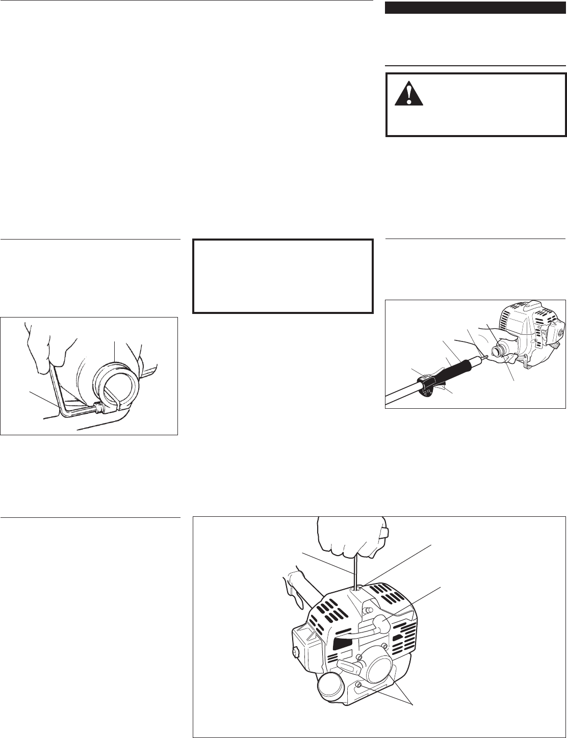
Remove The Cylinder Cover
Remove the spark plug boot.
Remove the two lower cylinder cover
screws.
Loosen the top cylinder cover screw
until the cover is free of the engine. (The
top cylinder cover screw is captive). Lift
the cylinder cover off of the engine.
1.
2.
3.
Connecting the Throttle Cable
Top Cylinder
Cover Screw
Hex Wrench
Spark Plug
Boot
Lower Cylinder
Cover Screws