


8
Assembly
IMPORTANT!
Blower tube installation affects blower
performance! Make sure the tubes and
nozzle are correctly assembled per
above, and that all connections are
tight. Blower tubes may come apart dur-
ing use unless tubes are aligned and
locked into place.
Place the blower upright on the 1.
ground or a sturdy work surface and
note parts orientation as shown in
Figure 7.
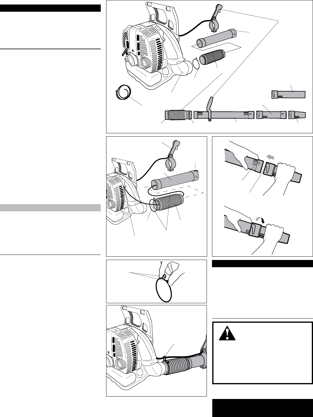
Remove static wire from package 2.
and x eyelet to right hand engine
cover screw. See Figure 8.
Turn the discharge tube out to a 3.
right angle and slip anti-static wire
through the 102mm clamp and ex-
ible tube.
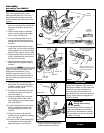
Install throttle cable holder just for-4.
ward of the 102 mm clamp, pinching
loops together to t over end of ex-
ible tube. See Figures 10A and 10B.
Slip the exible tube over the end of 5.
the 90° discharge tube, and secure
with the 102 mm clamp.
Slide the throttle assembly over the 6.
swivel tube. Do not tighten clamp at
this time.
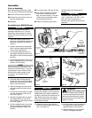
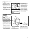
Insert the static wire through the 7.
swivel tube, then install and tighten
the 89mm clamp over the rotating
band on the swivel tube.
Fold the end of the static wire back 8.
over the connection of the swivel
tube. See Figure 8.
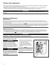
Grasp the straight tube, and push 9.
the straight tube over the swivel
tube locking pins securing the static
wire. See Figure 9.
Lock the straight tube to the swivel 10.
tube by rotating the straight tube
noting the alignment marks. See
Figure 9.
Grasp the nozzle, and push the 11.
nozzle over the straight tube locking
pins. See Figure 9.
Lock the nozzle to the straight tube 12.
by rotating the nozzle noting the
alignment marks. See Figure 9.
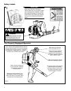
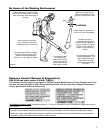
WARNING!
Danger from rotating
impeller!
Stop the engine before installing or
removing the blower tubes! Never
perform any maintenance or assem-
bly procedures on this unit while the
engine is running!
IMPORTANT!
This unit is equipped with a static
discharge reduction wire. This wire
helps direct static buildup into the air
stream reducing the felt amount to the
operator.
NOTE:
Check to make sure that the 90° dis-
charge tube swivels freely. If any
binding is present, loosen 102 mm
clamp and pull wire towards engine to
get more slack and recheck for free
movement.
The blower should now be ready
for use.
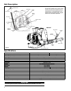
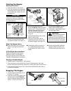
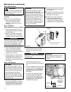
Assembling the EB854RT
Figure 7
Flexible Tube
Throttle
Assembly
89mm Clamp
102mm Clamp
Swivel Tube
Straight Tube
Swivel
Tube
90° Discharge
Tube
Anti-Static
Wire
Throttle Cable
Holder
Static Wire
Connector
Static Wire
Fold Wire
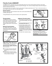
Flexible Tube
Swivel
Tube
Throttle
Assembly
Throttle
Cable Holder
Lock Pin
Lock Slot
Rotate clockwise to lock
making sure the 3 lines are
aligned on both tubes.
Align the lock pins with the
lock slots, and push the
tubes together.
Figure 9
Figure 8
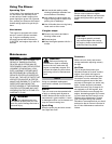
Adjust throttle assembly for best 13.
operator comfort, and tighten two
socket-head screws securely.
Loops
Figure 10A
Figure 10B
Throttle
Cable
Holder
Standard Nozzle
(ø65 mm)
O p t i o n a l
Long Nozzle
(ø74 mm)