14
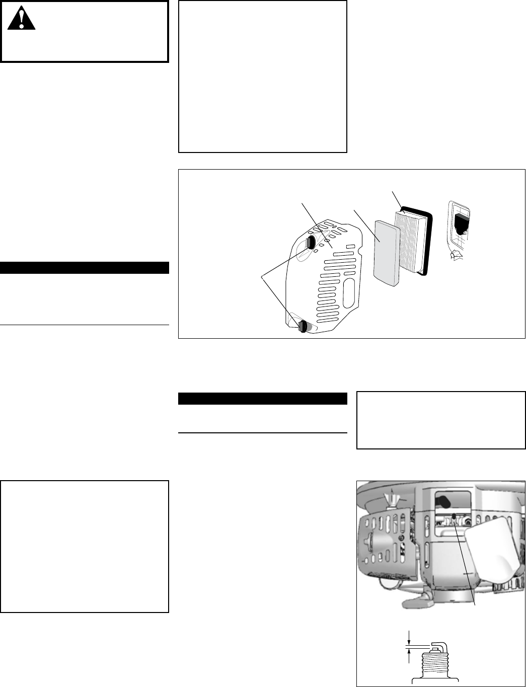
Install the lter element, pre-lter 6.
and cover in the reverse order of
removal.
To remove the cover, loosen the
thumbscrews and lift.
Air Cleaner
Element
Cover
Figure 19
Pre-Filter
Thumbscrews
Daily Maintenance
WARNING!
To reduce re hazard, keep
the engine and mufer free of dirt,
debris, and leaves.
Every 10 Hours
(more frequently in dusty conditions)
CAUTION!
Never operate the blower if the air
cleaner assembly is damaged or
missing!
Inspect the engine, tank, and hoses ■
for possible fuel leaks, and repair
as necessary.
Inspect the entire blower for loose,
■
damaged, or missing components,
and repair as necessary.
Carefully remove any accumula-
■
tions of dirt or debris from the
mufer and fuel tank. Dirt build-up
in these areas can lead to engine
overheating, re or premature wear.
IMPORTANT!
Direct the air stream at the inside face
of the lter only!
CAUTION!
The engine is cooled by air drawn
into the air intake cover on the
blower housing. The blower fan then
pushes the cooling air through an
opening in the fan housing, forcing it
past the cylinder cooling ns. Failure
to keep the cooling system and its
passages clear of debris will likely
result in engine overheating, a major
cause of serious engine problems
that can lead to failure.
Prior to each workday, perform the
following:
Remove all dirt and debris from
■
blower exterior and the engine.
Check the cooling ns and air
cleaner for clogging and clean as
necessary.
Remove the air cleaner cover by 1.
loosening the thumbscrews and lift-
ing. See Figure 19.
Remove and inspect the pre-lter. 2.
If the pre-lter is torn or otherwise
damaged, replace it with a new one.
Clean the pre-lter with soap and 3.
water. Let dry before reinstalling.
Inspect the air cleaner element. If 4.
the element is damaged or distorted,
replace it with a new one.
Tap lter gently on a hard surface to 5.
dislodge debris from element or use
compressed air from the inside to
blow debris out and away from the air
lter element.
IMPORTANT!
The blower uses a special high capac-
ity dry-type air lter element. The lter
should not be cleaned with a liquid
cleaner and must NEVER be oiled!
Maintenance (continued)
Counter-clockwise
to remove.
Clean the spark
plug and check
the gap at the
electrode.
spark plug gap--all models
0.6 mm
(0.024 in.)
Figure 20
NGK CMR5H
Every 10/15 Hours
CAUTION!
Never allow dirt or debris to enter
the cylinder bore! Before removing
the spark plug, thoroughly clean the
spark plug and cylinder head area!
Allow the engine to cool before
servicing the spark plug! Cylinder
threads can be damaged by tighten-
ing or loosening the spark plug while
the engine is hot!
Use the spark plug wrench to 1.
remove the spark plug. (See Figure
20)
Clean and adjust the spark plug gap 2.
to 0.6mm (0.024”). If the plug must
be replaced, use a NGK CMR5H or
equivalent type plug of the correct
heat range.
Install the spark plug nger-tight in 3.
the cylinder head, then tighten it
rmly with the spark plug wrench. If
a torque wrench is available, torque
the spark plug to 16.7-18.6 Nm
(148-165 inch- pounds).
Replace the spark plug annually:
■
Use only NGK CMR5H or equivalent
resistor type spark plug of the cor-
rect heat range. Set spark plug elec-
trode gap to 0.6 mm (0.024 inch)
.


