


9
English
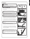
WARNING
Never perform maintenance or assembly procedures with en-
gine running or serious personal injury may result.
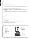
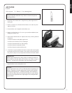
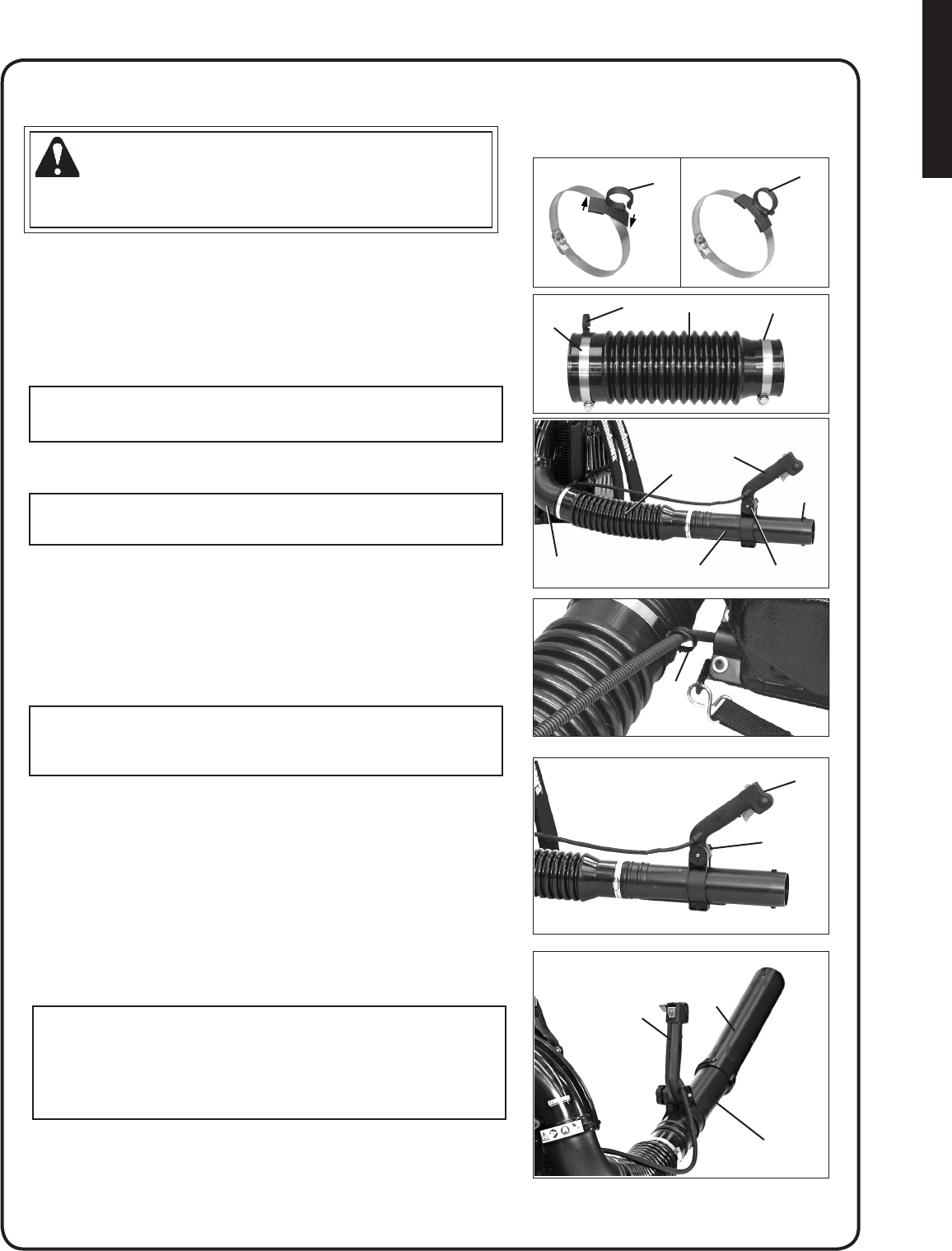
InsTall bloWer pIpes
Place guide loop (G) across elbow clamp, and turn until clips fully
engage clamp band.
Assemble clamps (A) onto both ends of exible pipe (B).
NOTE
Clamp with cable guide loop (G) ts elbow end of exible pipe.
Assemble swivel pipe (C) into exible pipe (B).
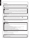
NOTE
Assure throttle cable is not twisted before installing handle (E).
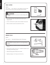
Position cable between the elbow (D) and frame and along the top of
the exible pipe. Loosen knob (H) on handle (E). Align notch in handle
with tabs (F). Install onto swivel pipe (C) past long ridges in pipe.
Assemble exible pipe (B) to elbow (D) on blower and tighten clamps
(A). Position guide loop (G) on inside (blower side) of exible tube.
NOTE
A light lubricant may be used to ease assembly of exible pipe to
blower elbow.
Clip throttle cable into throttle cable guide loop (G).
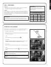
Move handle (E) to desired position. Tighten knob (H) hand tight.
Assemble straight pipe (I) onto swivel pipe (C), until you feel light
resistance. Do not force connection. Hold swivel pipe and turn straight
pipe clockwise, engaging positive locking channels, until connection is
rm. Do not force connection.
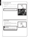
Assemble straight pipe (J) to straight pipe (I) as in step 8.
NOTE
Blower use will eventually loosen pipe connections. Exclusive
positive locking system allows pipes to be tightened. If loosening
occurs, remove two straight pipes and install according to instruc-
tions 8 & 9.
1.
2.
3.
4.
5.
6.
7.
8.
9.
E
I
C
E
B
H
F
D
G
E
H
G
A
A
B
G
C
G
assembly