


9
9
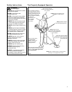
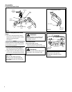
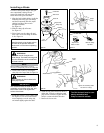
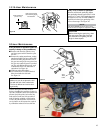
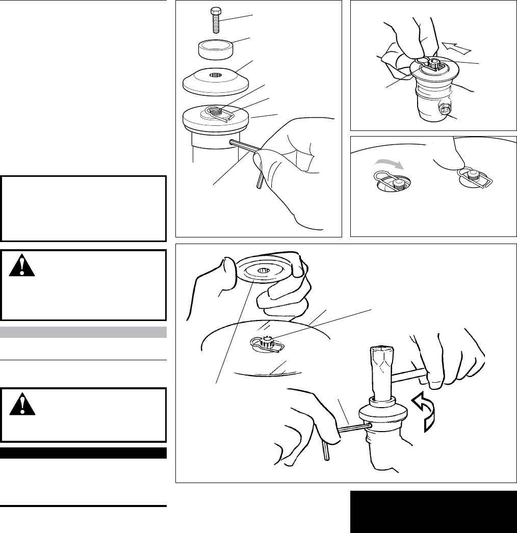
Turn the C3410 upside down so the gear
case output shaft is facing UP and
remove the shaft bolt, bolt guard and
holder B from the gear case shaft.
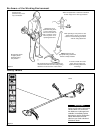
1. Align the hole in blade holder A with the
matching hole in the gear case flange
and then temporarily lock the output
shaft by inserting a hex wrench
through both holes.
See Figure 12.
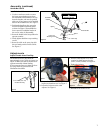
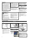
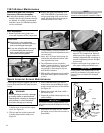
2. Slide the safety clip off-center.
See Figure 13.
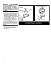
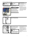
3. Fit the blade over the safety clip and
then center it over the flange on holder
A. See Figure 14.
Installing a Blade
NOTE:
When installing certain blades, it may be
necessary to temporarily remove the safety clip.
CAUTION!
Install the blade so its printed surface
is visible to the operator when the
brushcutter is in the normal operating
position.
WARNING!
The blade must t at against the
holder ange. The blade mounting hole
must be centered over the raised boss
on blade holder A.
WARNING!
Never operate the C3410 without the
safety clip in place!
4.
Lock the blade in place by centering the
safety clip on the output shaft. See Figure 14.
IMPORTANT!
The machined recess in holder B must
completely surround the safety clip, and
both holders must be at against the
surface of the blade.
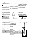
6. Install the bolt guard and then the blade re-
taining bolt. Using the combination spark
plug wrench/screwdriver, tighten the bolt
firmly in a counter-clockwise direction.
7. Remove the hex wrench.
Slide the safety clip off-center
Slip the Saw
Blade In Place
Slide the Safety
Clip Back
Shaft Bolt
Bolt Guard
Holder B
Output Shaft
Holder A
Hex
Wrench
Figure 12
Blade
Hex Wrench
Blade Holder B
Tighten the assembly (blade
not shown for clarity)
Figure 15
Safety Clip
Safety
Clip
Output
Shaft
Figure 13
Figure 14
Output
Shaft
The C3410 should now be com-
pletely assembled and
ready for use with a blade.
5. Install blade holder B on the output shaft.
See Figure 15. The recess in the holder
must completely cover the safety clip,
and must fit tightly against the blade.