


16
16
341033
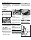
139/150-Hour Maintenance
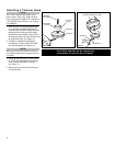
Valve Adjustment
1. Remove cylinder cover, rocker arm
cover, and set piston at TDC-compresion.
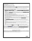
2. Loosen adjuster locknut so that the 2.5
mm Allen socket head adjustment screw
can turn freely.
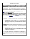
3. Insert .004" (0.10 mm) feeler gauge for
both intake and exhaust between valve
stem tip and rocker arm.
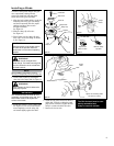
4. Turn adjustment screw (clockwise =
tighter, counter-clockwise = looser) until
feeler gauge is almost snug. Back off
6. Turn engine over several times, and
return to TDC-compression. Recheck
with proper feeler gauge to make sure
clearance adjustment did not change as
a result of tightening locknut. Readjust
as necessary.
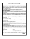
7. Replace rocker arm cover gasket to as-
sure proper sealing and install cover.
IMPORTANT!
If new gasket is not available and/or old
gasket is not damaged, old gasket may be
reused. Never use cracked or damaged
gaskets!
CAUTION!
n Performing a valve adjustment
incorrectly may cause hard starting
and/or can damage the engine.
n If you are unfamiliar with this engine
or uncomfortable with this proce-
dure, consult with an authorized
Shindaiwa servicing dealer.
just enough to allow gauge to slip out
with limited resistance.
5. While holding adjustment screw in place
with Allen driver, tighten locknut with
wrench.
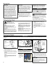
Maintenance after rst 139-hours,
then every 150-hours thereafter.
n Combustion chamber should be decar-
bonized, and the valve clearance should
be adjusted. It is highly recommended
that this is done by a Shindaiwa-trained
service technician.
n
Replace the spark plug annually: Use
only NGK CMR5H or equivalent resis-
tor type spark plug of the correct heat
range. Set spark plug electrode gap to
0.024-0.028 inch (0.6 -0.7 mm).
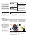
Spark Arrester Screen Maintenance
If the engine becomes sluggish and low on
power, check and clean the spark arrester
screen.
Never operate the unit with a damage
or missing mufer or spark arrester!
Operating with a missing or damaged
spark arrester is a re hazard and
could also damage your hearing.
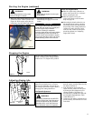
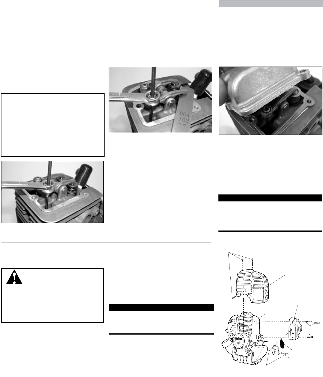
3. With a small flat bladed screwdriver
remove the 2 screws holding the spark
arrester screen and cover to the muffler.
See Figure 32.
4. Remove the screen and clean it with a
stiff bristle brush.
5. Inspect the cylinder exhaust port for any
carbon buildup.
6. Reassemble the spark arrester, muffler
and engine cover in the reverse order of
disassembly.
IMPORTANT!
If you note excessive carbon buildup, con-
sult with an authorized Shindaiwa servicing
dealer.
WARNING!
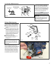
1. With a 3 mm hex wrench remove the
3 engine cover screws and the engine
cover. See Figure 32.
2. With a 4 mm hex wrench remove the
3 muffler bolts and the muffler. See
Figure 32.
Engine Cover
Screws
Figure 32
Cover
Mufer
Mufer
Gasket
Mufer
Bolts
Spark Arrester
Screen
Spark Arrester
Cover
Cover
Screws
NOTE:
The NGK CMR5H also meets the require-
ments for electro magnetic compliance (EMC).