


Handlebar and Throttle assemblyŶ
Handlebar C unit
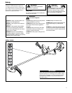
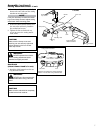
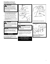
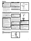
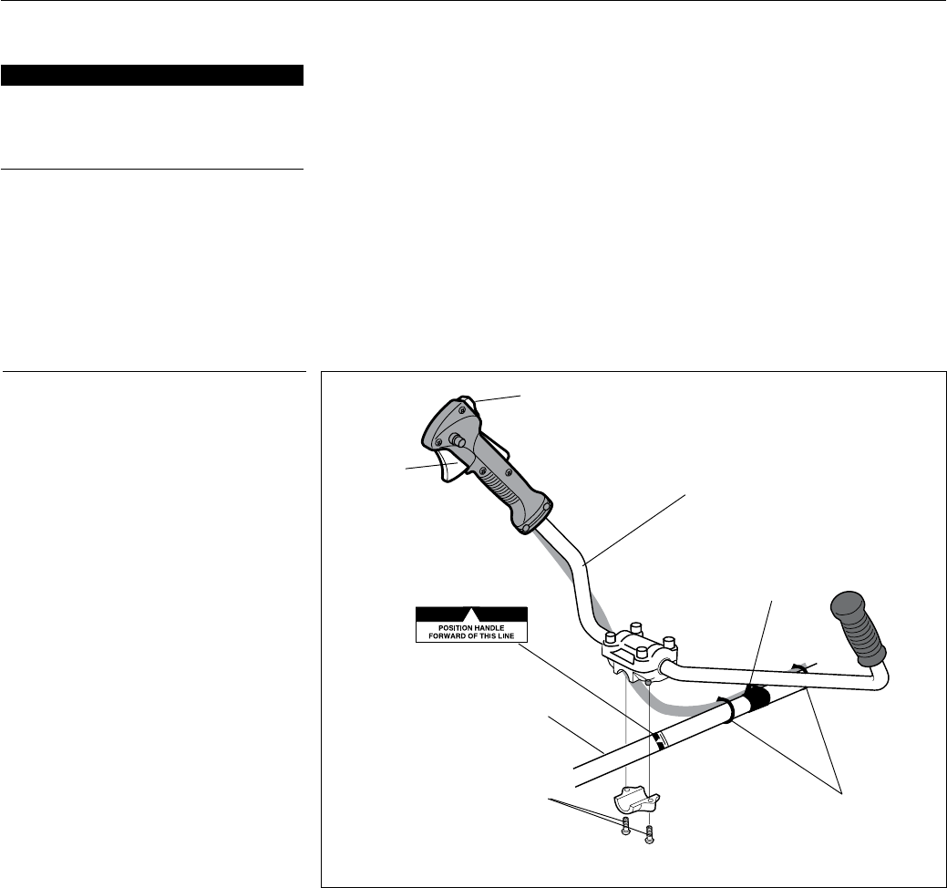
Install the handlebar:
Use the 4 mm hex wrench to remove the 1.
lower cap retaining screws from the
handlebar bracket. Remove the cap
from the bracket.
Position the handle on the outer tube for-2.
ward of Handle Positioning Label as
shown. Reassemble the lower cap to the
handlebar bracket in the reverse order
of disassembly.
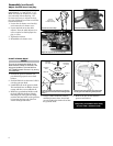
Locate the handle in the best position for 3.
operator comfort.
Firmly tighten both lower cap retaining 4.
screws.
Secure the cable to the outer pipe with the 5.
2 bands as the illustration shows. The 2
bands are in the tool bag.
Outer tube
Lower cap
retaining
screws
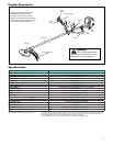
Handlebar
Ignition switch
Throttle
trigger
Hanger
Mounting the brushcutter handlebar
Handle positioning
label
Bands
6
Assembly
This unit comes fully assembled with the
exception of the cutting attachment shield
and cutting attachment.
Prior to Assembly
Before assembling, make sure you have all
the components required for a complete
unit and inspect unit and components for
any damage.
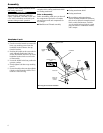
Engine and shaft assembly
Ŷ
Cutting attachment shieldŶ
Cutting attachmentŶ
Kit containing cutting attachment Ŷ
shield, mounting bracket and hardware,
this owner’s/operator’s manual and tool
kit for routine maintenance. Tool kits
vary by model and may include a spark
plug/screwdriver combination wrench,
and a scraper.
IMPORTANT!
The terms “left”, “left-hand”, and “LH”;
“right”, “right-hand”, and “RH”; “front” and
“rear” refer to directions as viewed by the
operator during normal operation.
This unit comes fully assembled with the
exception of the cutting attachment shield
and cutting attachment.