


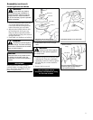
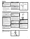
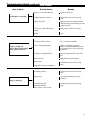

)XHO¿OWHUPDLQWHQDQFH
)XHO¿OWHUHOHPHQW
Hooked wire
17
Maintenance (continued)
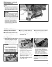
50-hour maintenance
Remove and replace the fuel filter
element.
Use a hooked wire to extract the fuel filter
Ŷ
from inside the fuel tank. Inspect the fuel
filter element. If it shows signs of contam-
ination, replace with a genuine Shindaiwa
replacement fuel filter element.
CAUTION!
Make sure you do not pierce the fuel line
with the end of the hooked wire. The line
is delicate and can be damaged easily.
139/150-Hour Maintenance
Maintenance after first 139-hours,
then every 150-hours thereafter.
Combustion chamber should be decar-
Ŷ
bonized, and the valve clearance should
be adjusted. It is highly recommended
that this is done by a Shindaiwa-trained
service technician.
Replace the spark plug annually: Use
Ŷ
only the type recommended in the
”Specifications” section or an equivalent
resistor type spark plug of the correct
heat range. Set spark plug electrode
gap to 0.6 -0.7 mm.
The valve clearance should be adjusted
Ŷ
annually or every 135 hours. It is
highly recommended that this is
done by a Shindaiwa-trained service
technician.
Before reinstalling the new filter element,
inspect the condition of all the fuel system
components (fuel pick-up line, fuel return
line, tank vent line, tank vent, fuel cap
and fuel tank). If damage, splitting or
deterioration is noted, the unit should
be removed from service until it can be
inspected or repaired by a Shindaiwa-
trained service technician.
IMPORTANT!
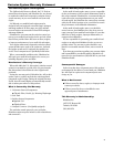
If a new gasket is not available and/or the
old gasket is not damaged, the old gasket
may be reused. Never use cracked or dam-
aged gaskets!
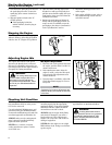
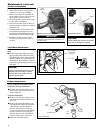
Turn engine over several times, and 6.
returnthe to TDC-compression.
Recheck with proper feeler gauge to
make sure clearance adjustment did
not change as a result of tightening the
locknut. Readjust as necessary.
Replace rocker arm cover gasket to 7.
assure proper sealing and install cover.
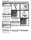
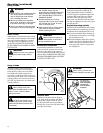
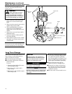
Remove cylinder cover, rocker arm cover, 1.
and spark plug.
Rotate the crankshaft
while observing the piston through the
spark plug opening. When the piston
is at the top of the compression stroke
(TDC), the valves can be adjusted.
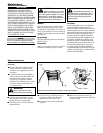
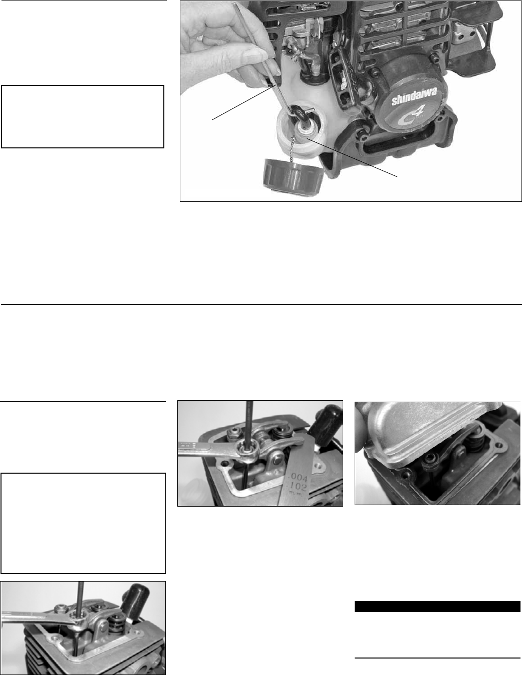
Loosen adjuster locknut so that the 2.
2.5 mm Allen socket head adjustment
screw can turn freely.
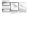
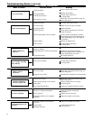
Insert 0.10 mm feeler gauge between 3.
valve stem tip and rocker arm.
Turn adjustment screw (clockwise = 4.
tighter, counter-clockwise = looser)
until feeler gauge is almost snug. Back
off just enough to allow gauge to slip
out with limited resistance.
While holding the adjustment screw in 5.
place with the Allen driver, tighten the
locknut with a wrench.
CAUTION!
Performing a valve adjustment
Ŷ
incorrectly may cause hard starting
and/or can damage the engine.
If you are unfamiliar with this
Ŷ
engine or uncomfortable with this
procedure, consult with an autho-
rized Shindaiwa servicing dealer.
Valve Adjustment