


9
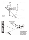
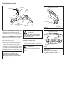
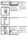
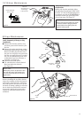
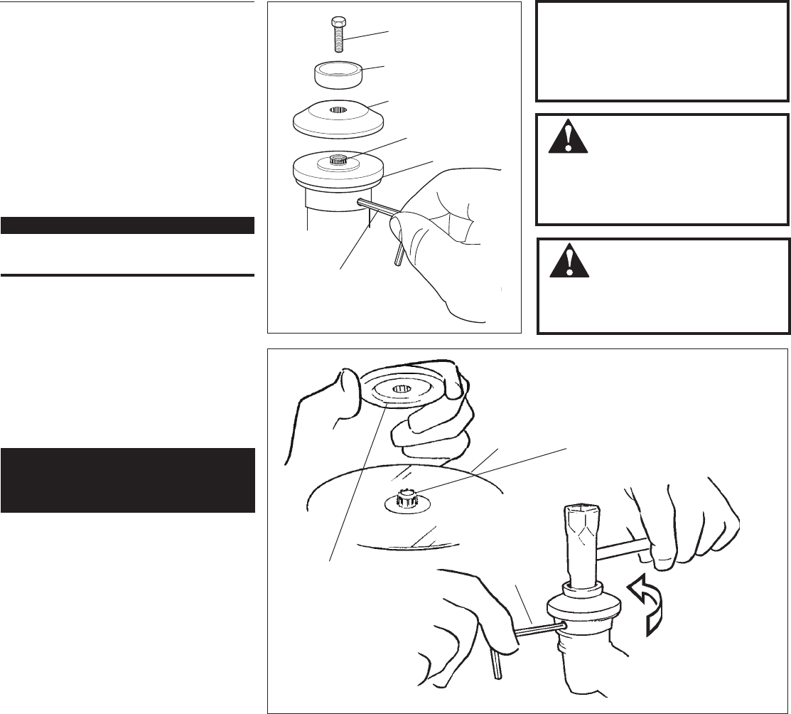
Turn the C242 upside down so the gear
case output shaft is facing UP and
remove the shaft bolt, bolt guard and
holder B from the gear case shaft.
1. Align the hole in blade holder A with the
matching hole in the gear case flange
and then temporarily lock the output
shaft by inserting a hex wrench
through both holes.
See Figure 12.
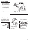
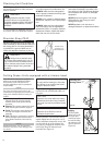
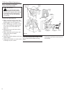
2. Fit the blade over the flange on holder
A. See Figure 13.
Installing a Blade
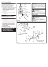
CAUTION!
Install the blade so its printed surface
is visible to the operator when the
brushcutter is in the normal operating
position.
WARNING!
The blade must t at against the
holder ange. The blade mounting hole
must be centered over the raised boss
on blade holder A.
IMPORTANT!
Both holders must be at against the
surface of the blade.
3. Install blade holder B on the output
shaft. See Figure 13.
4. Install the bolt guard and then the blade
retaining bolt. Using the combination
spark plug wrench/screwdriver, tighten
the bolt firmly in a counter-clockwise
direction. The holder B must fit flush
against the blade.
5. Remove the hex wrench.
Shaft Bolt
Bolt Guard
Holder B
Output Shaft
Holder A
Figure 12
Blade
Hex Wrench
Blade Holder B
Tighten the assembly (blade
not shown for clarity)
Figure 13
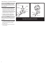
Output
Shaft
The C242 should now be com-
pletely assembled and
ready for use with a blade.
Hex
Wrench
WARNING!
Holder B must t ush against the
blade with the splines engaged to the
output shaft.