


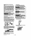
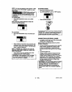

NOTE: Make aura red batteey boots cover
positive battery oable ton'ninals at battery mid
emkmoid
Attimh one end of the negatNe (black) cable te the
negative (-) terminal on the battery.
Attach the other end of the negative (blaok)cable
to the tYanteas shown. Install the star washer
between the cable and the frame,
IMPORTAN'r: See Caution on page 10
before assembling batter/.
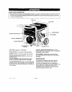
GROUNDING THE GENERATOR
A grounding lug IssuppNed with the generator for use
when required by ]oQelelectrical ordinances. Referto
article 250 of the National Ek_ctrlcalCode to clarity
any needed grounding information. Your Ioeel electric
oompany or s certified electflclan should be able to
help you with this informetlon.
NOTE:Yourengineis already g_undedtOthe frame
bya groundingstrap.
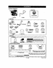
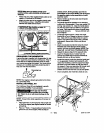
INSTALLING WHEEL KIT
The Craftsman Wheel Kit was dse|gned to gmmly
improve the portabll/ty of your generator.
JI UlJ?-'o
kit. Fall
engine.
assembling the portability
kit. Failure to die so will cause damxge to the
NOTE: AJwaysfollow stets regulations for proper ell
dispcesi.
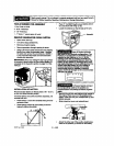
Place generator on level ground; d_dn allgas and
oil fromthe engine (sea engine manual for ocrmct
pressure).
• Piaceal'thiokxl"squampleceofwoodonthe
ground In front ofthe engine, With the help of
11 -- ENG
anether potash. _t the generat_ and rset the
rm_l abl_er en the wood. _ This will support
the gaecane engine dudnO n_mrnbly and meke
assembly easier.
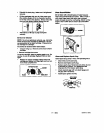
• Plaoe ahandle cap (7) onto _ end of handle
prior toInatalletfon,
• The handle should be installed on the eleetdcal
outlet end of the generator.. Place one washer (12)
on long cap screws (1t). Align the handle brack-
ets with the upper holes pro-drilledin the gerlem-
forframe. Place mentioned screws through frame
and handle brackets. Secure with lock nuts
(8)and tighten.
• Locate the engine support. Place one wheel
_'ackst (4) 0_1top of support as shown in Ilisetra-
tion. Align with the pre,.drilledholes in support.
Piece 2 cap screws (9) through holes in bracket
and support. Secure with 2 lock nuts (8)end
tighten.
• Insert nee shoulder bolt (2) into Wheel(1). Insert
threaded end of her through wheel bracket,
secure with look nut (3) and tighten. NOTE: The
wheel wHI not rub frame If instannod properly,
• Repeat the above steps for the opposite side.
• insert the threaded stud of rubberfoot (10)
through the middle hole of the foot bracket (5),
Secure with lock nut(8) and t_ghten.
• Lecete the support under the elestrioal outlet end
of the generator. Positionfoot bracket (5), with
rubber foot instead, under the support and al)gn
the holes In the foot bracket (5) with the slots in
the support. Place one sap screw (9) through each
slot in the support end the holes in the foot
bracket. Secure with the lock nuts (8) and tighten.
• Once completed, the wheel Mt is ready for use,
1
12
8
g
1o
DtoJ|lr _o_