


8
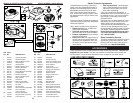
The operation of any lawn
mower can result in foreign
objects thrown into the
eyes, which can result in
severe eye damage. Always
wear safety glasses or eye shields while
operating your lawn mower or performing
any ad just ments or repairs. We recom-
mend standard safety glasses or a wide
vision safety mask worn over spectacles.
HOW TO USE YOUR LAWN MOWER
ENGINE SPEED
Engine speed was set at the factory for
optimum performance. It is not adjustable.
ENGINE ZONE CONTROL
CAUTION: Federal regulations re quire
an engine control to be installed on this
lawn mower in order to minimize the
risk of blade contact injury. Do not un der
any circumstances attempt to de feat the
func tion of the operator con trol. The blade
turns when the engine is running.
• Your lawn mower is equipped with an
operator pres ence control bar which
requires the operator to be positioned
behind the lawn mower handle to start
and operate the lawn mower.
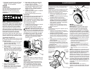
DRIVE CONTROL
• Self-propelling is controlled by hold-
ing the operator presence control bar
down to the handle and pulling the drive
control lever rearward to the handle.
The farther toward the handle the lever
is pulled, the faster the unit will travel.
• Forward motion will stop when either
the operator presence control bar or
drive control lever are released. To stop
forward motion without stop ping engine,
re lease the drive control lever only. Hold
op er a tor presence control bar down
against handle to con tin ue mowing
without self-propelling.
NOTE: If after releasing the drive control the
mower will not roll backwards, push the mow-
er forward slightly to disengage drive wheels.
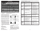
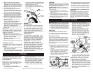
DRIVE CONTROL ADJUSTMENT
Over time, the drive control system may be-
come “loose”, resulting in decreased speed.
There is a turnbuckle on the un der side of the
drive control housing to increase tension on
the drive cable. Pro ceed as follows:
1. Turn unit off and disconnect spark plug
wire from spark plug.
2. Turn nut on underside of drive control
to increase drive speed.
3. Operate mower to test drive speed.
Readjust as required.
4. If condition fails to improve after the
above steps (forward speed remains
the same), your drive belt is worn and
should be re placed.
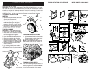
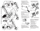
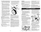
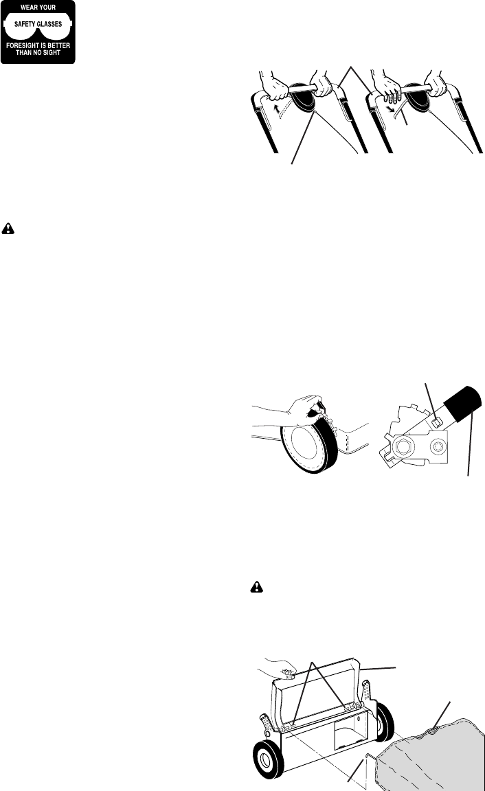
TO ATTACH GRASS CATCH ER
1. Lift the rear door of the lawn mower
and place the grass catcher frame side
hooks onto the door pivot pins.
2. The grass catcher is secured to the lawn
mower housing when the rear door is
lowered onto the grass catch er frame.
CAUTION: Do not run your lawn mower
with out mulcher plug or approved grass
catch er in place. Never at tempt to op-
er ate the lawn mower with the rear door
re moved or propped open.
Pivot pins
Rear
door
Grass
catcher
handle
Catcher frame hook
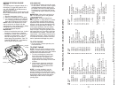
TO ADJUST CUTTING HEIGHT
Raise wheels for low cut and lower wheels
for high cut, adjust cutting height to suit
your requirements. Me di um position is
best for most lawns.
• To change cutting height, squeeze ad-
juster lever to ward wheel. Move wheel
up or down to suit your re quire ments. Be
sure all wheels are in the same setting.
NOTE: Adjuster is properly positioned when
plate tab inserts into hole in lever. Also, 9-
position adjusters (if so equipped) allow lever
to be positioned between the plate tabs.
TO
ENGAGE
DRIVE
CONTROL
Drive
control
lever
DRIVE
CONTROL
DISENGAGED
Operator presence control bar
Adjustment
turnbuckle
LEVER BACKWARD
TO LOWER MOWER
LEVER FORWARD TO RAISE MOWER
Plate tab
Lever
41
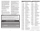
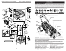
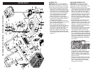
NOTE: All component dimensions given in U.S. inches. 1 inch = 25.4 mm.
IMPORTANT: Use only Original Equipment Manufacturer (O.E.M.) replacement parts. Failure to do so could be hazardous, damage your lawn mower and void your warranty.
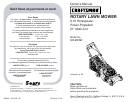
CRAFTSMAN ROTARY LAWN MOWER - - MODEL NUMBER 917.370721
KEY PART
NO. NO. DESCRIPTION
28 12000058 E-Ring 7/16
29 189403 Cover, Dust, Wheel
30 73800400 Nut, Hex
31 175098 Pawl
32 194231X460 Wheel & Tire Assembly, Rear 8 x 1-3/4
33 83923 Nut, Flangelock 3/8-16
34 175103 Gear
35 175105 Retainer, Drive, LH
36 175104 Disc, Drive
37 184172 Seal, Friction
38 175102 Retainer, Drive, RH
40 194230X460 Wheel & Tire Assembly, Front 8 x 1-3/4
41 188330 Pinion Assembly, RH
43 188331 Pinion Assembly, LH
44 183688 V-Belt
47 67725 Washer
51 187530 *Case, Lower
52 187531 *Case, Upper
53 187532 Gear, 24 Teeth
54 187533 Shaft, Input
55 183505 Wire, Formed
56 183506 Bearing, Ball
57 183508 Seal, Output Shaft
58 183509 Washer
59 183511 Bushing
60 197385 Shaft, Output
61 183513 Screw
62 183514 Seal, Input Shaft
* Use Dow Corning #709 to reseal Gear Case Halves.
1 195989 Drive Control Assembly (Includes Cable)
2 195745 Cover, Top
3 187353 Pulley
4 188281 Lever, Drive Control
5 195744 Cover, Bottom
6 181698 Screw
7 400235X479 Mounting Bracket
8 184987 Cap, Bottom
9 196002 Cable, Drive
10 194212 Decal, Drive Control Operation
11 188291 Spring, Torsion
12 187653 Screw
13 193354 Gear Case Assembly, Complete
14 193443 Pulley, Drive
15 197235 Kit, Wheel Adjuster Assembly, RH
(Includes Knob and Bearing)
16 197234 Kit, Wheel Adjuster Assembly, LH
(Includes Knob and Bearing)
17 166785 Nut, Hex
18 168360X004 Spring, Selector
19 701037 Knob, Selector Spring
20 160835X007 Bracket, Wheel Adjusting
21 160828 Bolt, Shoulder, Hex Head
22 169911 Bearing, Ball
23 186578X004 Axle Arm Assembly, RH
24 186577X004 Axle Arm Assembly, LH
25 199775X428 Cover, Drive
26 750634 Screw, Threaded, Rolled #10-25 x .50
27 183901 Spacer
KEY PART
NO. NO. DESCRIPTION