


ASSEMBLY
TOOLS REQUIRED FOR ASSEMBLY
A socket wrench set will make assembly easier. Standard
wrench sizes are listed.
(1) 9/16" wrench
(2) 7/16" wrenches
(1) 1/2" wrench
(1) 3/4" wrench
Pliers
Tire pressure gauge
Screwdriver
Utility knife
When right and left hand is mentioned in this manual, it
means when you are in the operating position (seated
behind the steering wheel).
TO REMOVE UNIT FROM CARTON
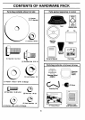
UNPACK CARTON
• Remove all accessible loose parts and parts cartons
from carton (See page 6).
• Cut along dotted linesonthe carton, from top tobottom,
all four corners of carton and lay panels fiat.
• Check for any additional loose parts or cartons and
remove.
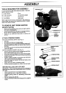
ATTACH STEERING WHEEL
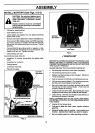
POSITION STEERING SHAFT (See Fig. 1) -
• Lift hood.
• Pull steering shaft up to engage gears.
• Push steering clip through hole on steering shaft at 45°
(hole is located under dash and above lower steering
bushing).
• Push steering clip onto steering shaft until steering clip
snaps into place.
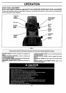
INSTALL STEERING WHEEL (See Fig. 2) -
• Slide the steering sleeve over the steering shaft (Bot-
tom of sleeve goes over ring on dash).
• Slidesteering wheel adapter onto uppersteering shaft.
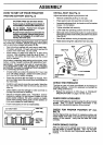
• Position front wheels of the tractor sothey are pointing
straight forward.
• Position steering wheel so cross bars are horizontal
(left to right) andslide onto adapter.
• Assemble large flat washer and 3/8-24 Iocknut and
tighten securely.
• Snap insert into center of steering wheel.
• Remove protective plastic from tractor hood and grill.
BEFORE ROLLING UNIT OFF SKID
IMPORTANT: CHECK FOR AND REMOVEANY STAPLES IN
SKID THAT MAYPUNCTURE TIRES WHEREUNITIS TOROLL
OFF SKID.
• Raise mower lift lever to its highest position.
• Place gearshift lever in "NEUTRAL" position.
• Release parking brake by depressing clutch/brake
pedal.
• Roll unit backwards off skid.
• Remove banding holding discharge guard up against
tractor.
STEERING SHAFT
;TEERING SHAFT
STEERING CLIP
LOWER
BUSHING
FIG. 1
STEERING WHEEL
INSERT
LOCKNUT
WASHER
_STEERING WHEEL
STEERING WHEEL
STEERING SLEEVE
STEERING SHAFT
FIG. 2