


SERVICE AND ADJUSTMENTS
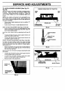
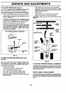
TO ADJUST BRAKE (See Fig. 27)
Your unit is equipped with an adjustable brake system
which is mounted on the right side of the transaxle.
If unit requires more than six (6) feet stoppingdistance at
high speed in highest gear, then brake mustbe adjusted.
• Depress clutch/brake pedal and engage parking brake.
• Measure distance between brake operating arm and
nut "A" on brake rod.
• If distance is other than 1-5/8", disengage parking
brake, loosen jam nut and turn nut "A" until distance
becomes 1:5/8". Retighten jam nut against nut "A".
• Engage parking brake and recheck distance.
• Road test unit for proper stopping distance as stated
above. Readjust if necessary. If stopping distance is
still greater than six (6) feet in highest gear, further
maintenance is necessary. Contact your nearest
authorized service center.
WITH PARKING BRAKE "ENGAGED"
JAM NUT
OPERATING
ARM
FIG. 27
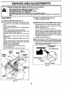
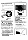
TO REPLACE MOTION DRIVE BELT (See
Fig. 28)
• Disconnect motion drive belt at frame belt keeper.
• Disconnect motion drive belt at engine pulley. Thread
belt below mower drive sheave and through engine belt
keeper and engine pulley.
• Remove belt.
• Install new belt by reversing above procedure.
• Make sure that belt is inside all belt keepers.
IMPORTANT: REPLACE ONLY WITH BELTLISTED INTHIS
MANUAL.
MOTION DRIVE BELT
ENGINE
PULLEY
MOWER DRIVE BELT
ENGINE
BELT
KEEPER
MOWER
DRIVE
SHEAVE
CLUTCH
PEDAL
SHAFT
MOWER UFT
SHAFT
CLUTCHING
IDLER
i FRAME BELT
'KEEPER
TRANSAXLE
PULLEY
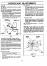
The tractor drive belt may be replaced without tools.
Park the tractor on level area. Engage parking brake.
For assistance, there is a belt installation guide decal on
bottom side of left footrest.
Engage parking brake.
Lower mower lift lever to "lowest" position.
Turn front wheels fully to left or right.
Disconnect mower drive belt at engine pulley.
Disconnect motion drive belt at clutching idler.
Disconnect motion drive belt at transaxle. Push above
transaxle pulley.
FIG. 28
TO ADJUST STEERING WHEEL ALIGNMENT
If steering wheel crossbars are not horizontal (left to right)
when wheels are positioned straightforward, remove steer-
ing wheel and reassemble per instructions in the Assembly
section of this manual.
FRONT WHEEL TOE-IN/CAMBER
The front wheel toe-in and camber are not adjustable on
yourtractor. Ifdamage has occuredto affectthefrontwheel
toe-in or camber, contact your nearest authorized service
center.
2O