


SERVICE AN[:) ADJUSTMENTS
ii ,,, 1111111,1 , ,,, ,i i111 ,i ,,i1,
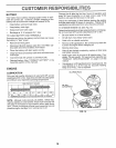
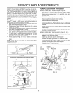
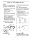
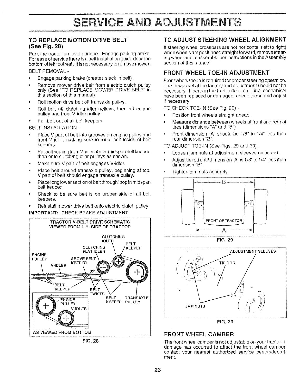
TO REPLACE MOTION DRIVE BELT
(See Fig. 28)
Park the tractor on level surface, Engage parking brake.
For ease of service there is a belt installation guide decat on
bottom of left footrest, ]tis not necessary to remove mower,
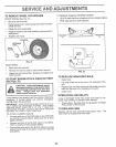
BELT REMOVAL -
o Engage parking brake (creates slack in belt)
o Remove mower drive belt from electric clutch pulley
REPLACE MOWER DRIVE BELT" Jn
only (See "TO
this section of this manual).
• Roll motion drive belt off transaxle pulley.
• Roll belt off clutching idler pulleys, then off engine
pulley and front V-idler pulley
° Pull belt out of all belt keepers.
BELT INSTALLATION -
• Place V part of belt into grooves on engine pulley and
front V-idler, making sure to route belt inside of belt
keepers,
• Put bett coming from V-idler above midspan bett keeper,
then onto clutching idler pu!teys as shown.
. Make sure V part of belt engages V-idler.
° Place beit around transaxle pulley, beginning at top,
V part of belt should engage transaxle pulley.
o Place long lower section of belt through loop in midspan
belt keeper.
o Check to be sure belt is on proper side of all belt
keepers.
• Reinstall mower drive belt onto electric clutch pulley
IMPORTANT: CHECK BRAKE ADJUSTMENT
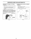
TRACTOR V-BELT DRIVE SCHEMATIC
VIEWED FROM LH, SIDE OF TRACTOR
CLUTCHING
IDLER
BELT
CLUTCHING tKEEPER
FLATIDLER
ENGINE
PULLEY 3ELT\
V-IDLER
KEEPER BELT
TWISTS
BELT TRANSAXLE
PULLEY KEEPER PULLEY
AS VIEWED FROM BOTTOM
FIG, 28
TO ADJUST STEERING WHEEL ALIGNMENT
If steering wheel crossbars are not horizontal (left to right)
when wheels are positioned straight forward, remove steer-
ing wheel and reassemble per instructions in the Assembly
section of this manual
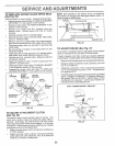
FRONT WHEEL TOE-IN ADJUSTMENT
Front wheel toe-in is required for proper steering operation.
Toe-in was set at the factory and adjustment should not be
necessary, if parts in the front axle or steering mechanism
have been replaced or damaged, check toe-in and adjust
if necessary.,
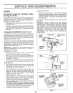
TO CHECK TOE-IN (See Fig 29) -
- Position front wheels straight ahead
. Measure distance between wheels at front and rear of
tires (dimensions "A" and "B").
o Front dimension "A" should be 1/8" to 1/4" less than
rear dimension "B"o
TO ADJUST TOE-IN (See Figs, 29 and 30) -
o Loosen jam nuts at adjustment sleeves on tie rod.,
• Adjust tie rod until dimension "A" is 1/8" to t/4" less than
dimension "B".
• Tighten jam nuts securely.,
FIG. 29
ADJUSTMENT SLEEVES
TIE ROD
i
JAM NUTS
FIG, 30
FRONT WHEEL CAMBER
The front wheel camber is not adjustable on your tractor, If
damage has occurred to affect the front wheel camber,
contact your nearest authorized service centeddepart-
menL
23