


6
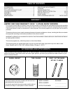
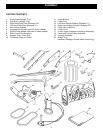
• Remove all parts and hardware packages from the
carton. Lay out parts and hardware and identify using
the illustrations on pages 4 and 5.
NOTE: Not all of the supplied parts and hardware
will be needed for your particular tractor. Unneeded
items may be discarded after you have completed
assembly.
REMOVAL OF PARTS FROM CARTON
(2) 7/16" Wrenches
(2) 1/2" Wrenches
(2) 9/16" Wrenches
(2) 3/4" Wrenches
(1) Knife
ADDITIONAL ITEMS REQUIRED
General Purpose Grease
TOOLS REQUIRED FOR ASSEMBLY
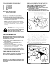
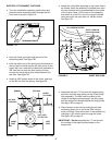
TRACTOR PREPARATION
Before performing these instructions, refer to the Service
and Adjustments section of your tractor owner's manual
for specific safety instructions.
• Allow engine, muffler and exhaust deflector to cool
before beginning.
• Remove any front or rear attachment which is
mounted to your tractor.
• Remove the mower deck. Refer to your tractor
owner's manual for removal instructions. Mark all
loose parts and save for reassembly.
• Remove the tractor hood and grill assembly. Refer to
your tractor owner's manual for removal instructions.
ITEMS REMOVED FROM TRACTOR
Store all parts that you remove from the tractor and do
not re-use while assembling the snow thrower.
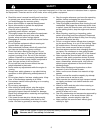
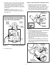
CAUTION: Before starting to assemble
the snow thrower, remove the spark plug
wire(s), set the parking brake and
remove the key from the tractor ignition.
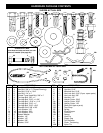
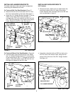
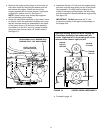
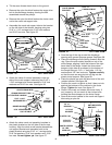
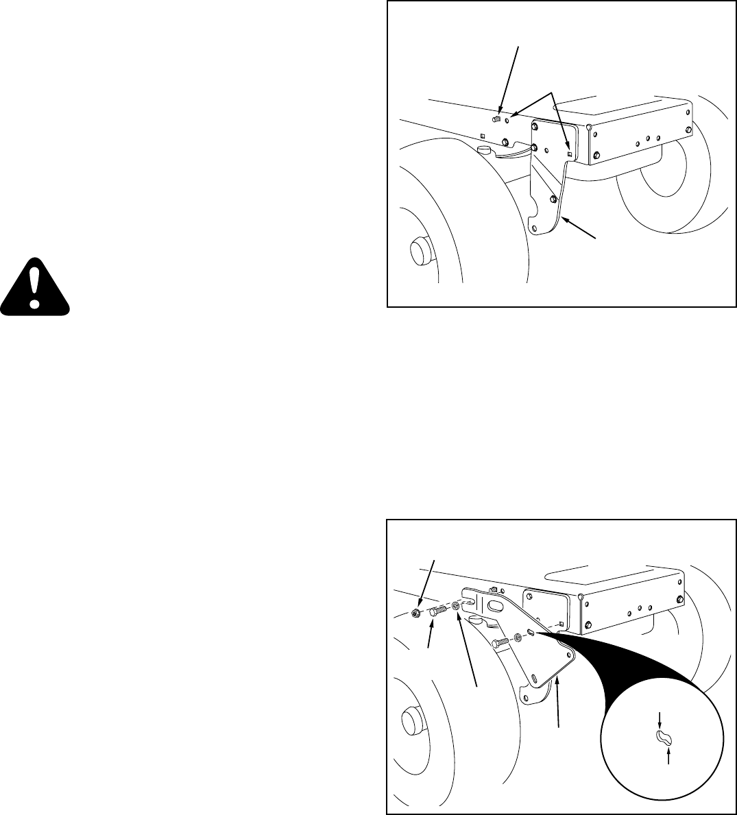
INSTALLING SIDE PLATES ON TRACTOR
FIGURE 2 RIGHT SIDE VIEW
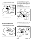
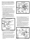
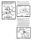
TRACTORS WITH FRAME MOUNTED FRONT
SUSPENSION BRACKETS (See figure 1.)
• Remove any bolts that are present in the two holes
shown as empty in figure 1.
• If there is a bolt in the third hole shown in figure 1,
remove the nut and washer but leave the bolt in place.
FIGURE 1 RIGHT SIDE VIEW
FRONT
SUSPENSION
BRACKET
REMOVE NUT & WASHER
AND LEAVE BOLT (IF PRESENT)
THESE HOLES
MUST BE EMPTY
Right hand (R.H.) and left hand (L.H.) side of the tractor
are determined from the operators position while seated
on the tractor.
• Assemble the R.H. Side Plate (marked "R") to the
two now empty holes in the side of the tractor frame.
Use two 3/8" x 1" hex bolts and 3/8" lock washers as
shown in figure 2. Repeat for the L.H. side.
• If you removed a nut and washer from the bolt in
figure 1, assemble a whizlock nut onto the bolt.
NOTE: If you remove the side plates, be sure to
reassemble all bolts to tractor frame .
3/8" x 1"
HEX BOLT
3/8" LOCK
WASHER
5/16" WHIZLOCK NUT
(IF BOLT IS PRESENT IN TRACTOR)
R.H. SIDE
PLATE
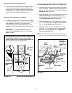
This end for
16" front tires
This end for all
smaller tires