


14
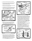
• Tilt the snow thrower back down to the ground.
• Remove the nylon tie which fastens the auger drive
belt to the discharge housing, leaving the belt
assembled around the pulleys.
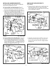
• Remove the nylon tie which fastens the chute crank
rod to the crank rod support tube.
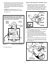
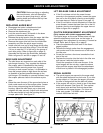
• Assemble the crank rod support tube to the bracket
on the left side of the thrower housing using two
5/16" x 1-1/4" carriage bolts, 5/16" lock washers
and 5/16" hex nuts. See figure 25.
5/16" HEX NUT
5/16" LOCK
WASHER
CHUTE CRANK
BRACKET
5/16" FLAT
WASHER
CHUTE
CRANK
ROD
ROD
SUPPORT
BRACKET
5/16" x 1"
CARRIAGE BOLT
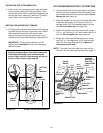
FIGURE 27 LEFT SIDE VIEW
FIGURE 28 RIGHT SIDE VIEW
CHUTE KEEPER
ANTI-ROTATION
BRACKET
1/4" HEX
LOCK NUT
1/4" FLAT
WASHER
1/4" x 1"
HEX BOLT
PLASTIC CAP
GREASED
SURFACE
FLANGE
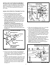
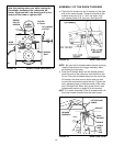
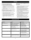
• Coat the top of the ring around the discharge
opening with general purpose grease. See figure 28.
• Place the discharge chute (facing forward) onto the
ring. Place the anti-rotation bracket on top of the
chute flange, aligning it with the holes on the right
hand side of the flange. Attach the three chute
keepers (right side up as shown) to the bottom of
the flange using six 1/4" x 1" hex bolts, 1/4" flat
washers and 1/4" hex lock nuts. Tighten carefully
so that the nuts are snug but do not dig into the
plastic chute keepers. See figure 28.
• Place the plastic cap onto the short end of the anti-
rotation bracket. See figure 28.
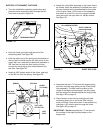
• Position the crank rod spiral so that it does not rub
against the bottoms of the notches in the chute
flange. Tighten the nuts. See figure 27.
• Check if the crank rod rotates the chute freely. If
not, loosen by 1/4 turn each of the six hex bolts
holding the chute keepers to the chute flange.
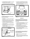
• Secure the control cables to the crank rod support
tube using a nylon tie.
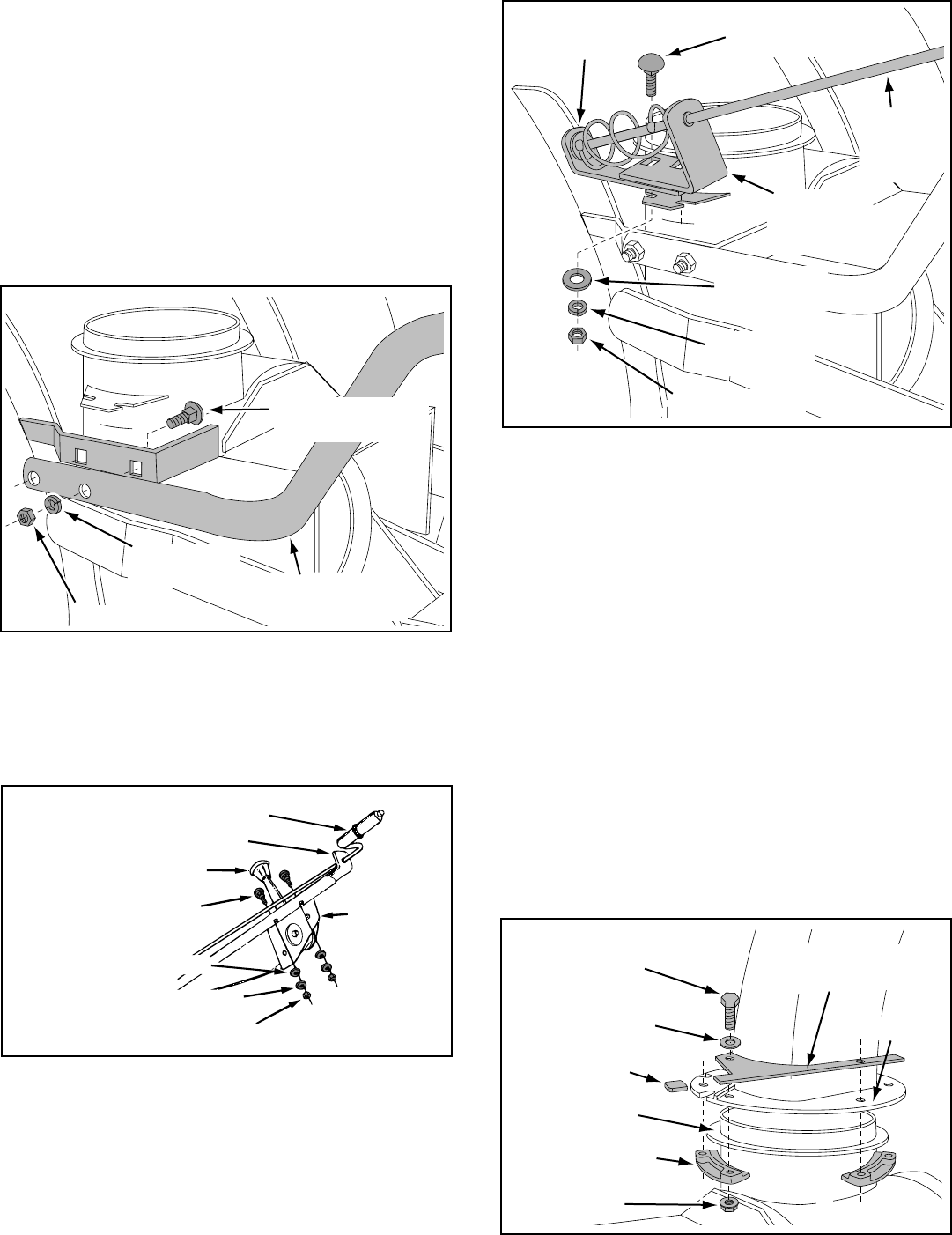
• Attach the chute crank rod assembly brackets to
the plastic bracket on the left side of the thrower
housing. Align the chute crank bracket beneath the
rod support bracket and assemble both to the
plastic bracket using two 5/16" x 1" carriage bolts,
5/16" flat washers, 5/16" lock washers and 5/16"
hex nuts. Do not tighten yet. See figure 27.
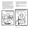
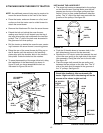
FIGURE 26 LEFT SIDE VIEW
CHUTE CRANK ROD
CRANK SUPPORT TUBE
TILT CONTROL HANDLE
5/16" x 1-3/4"
CARRIAGE BOLT
BOWED WASHER
5/16" LOCKWASHER
5/16" HEX NUT
TILT
CONTROL
ASSEMBLY
• Attach the chute tilt control assembly to the top
side of the crank support tube using two 5/16" x
1-3/4" carriage bolts, bowed washers, 5/16" lock
washers and 5/16" hex nuts. See figure 26.
5/16" HEX NUT
5/16" LOCK
WASHER
5/16" x 1-1/4"
CARRIAGE BOLT
CRANK ROD
SUPPORT TUBE
FIGURE 25 LEFT SIDE VIEW