


6
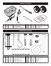
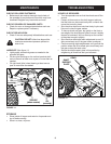
FIGURE 9
DEFAULT POSITION
EXTENDED
(IF INTERFERENCE)
FIGURE 8
1/4 x 1-3/4
HEX BOLT
1/4 NYLOCK NUT
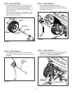
STEP 8: (SEE FIGURE 8)
• Assemble the two INNER hitch braces to the ow
control mounting tube using a 1/4" x 1-3/4" hex bolt
and a 1/4" nylock hex nut. TIGHTEN.
• TIGHTEN all nuts and bolts assembled up to this
point. Do not collapse tubes when tightening.
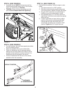
STEP 9: (SEE FIGURE 9)
• For most vehicles, the hitch tube assembly should be
left in the default position.
• Attach the spreader hitch to your vehicle hitch.
• Check for interference with the spreader directly
behind and out to both sides of the vehicle. Lift the
spreader at each position to make sure there is no
interference with the spreader's ow control.
• If there is interference with the rear of the vehicle,
extend the hitch tube assembly.
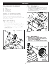
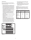
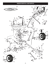
FLOW
CONTROL
ARM
OFF
ON
1
2
3
4
6
7
8
9
10
5
ADJUSTABLE
STOP
(SETTING "5")
ON
OFF
0
FIGURE 10
STEP 10: (SEE FIGURE 10)
• Calibrate the ow setting. Follow the steps in order
below.
1. Push ow control arm to "OFF" position.
2. Slide ow control mounting bracket along tube
until closure plate in bottom of hopper just closes.
3. Snug the 5/16" nylock hex nuts just enough to
hold ow control mounting bracket in place.
4. Set adjustable stop at "5". Pull ow control arm
against stop. Verify that closure plate has opened
about half way.
5. If closure plate does not open half way, adjust
position of ow control mounting bracket until
closure plate will open about half way at "5"
and will still close when arm is locked in "OFF"
position. Tighten the 5/16" nylock hex nuts.