


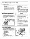

D. ATTACHING THE BAR AND CHAIN
_ICAUTION:!Wear protective gloves when han.
dling or operating your saw. The chain is sharp
and can cut you even when it isnot moving!
• Your saw is equipped with a Lo-Kick ® Guide
Bar and a Guard Link Chain designed to help
reduce kickback.
• Always use the Lo-Kick _ Guide Bar and the
Guard Link Chain specified for your chain
saw model, when replacing these parts.
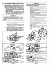
WARNING_
WARNING! / !'
Never try to install the bar upside down to avoid in-
creasing the hazard of kickback.
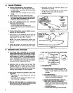
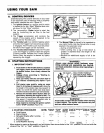
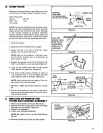
c. Hold chain with cutters facing as shown in
Figure 6.
d. Place chain over and behind the clutch
drum onto the sprocket,
e. Slide Guide Bar to the rear of the saw as far
as possible.
f, Fit the bottom of the drive links between
the teeth in the sprocket.
g. Start at the top of the bar and fit the chain
drive links into the around the Guide
groove
- Bar. Figure 6. '
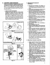
Do not start engine without guide bar and chain I h. Pull the Guide Bar forward until the chain is
completely assembled. Otherwise the clutch I snug in the guide bar groove Figure 7.
can come off and serious personal injury could / i Install the outer guide plate "Figure3
..................................result: .............................:.................................................................:...........................................................................................J_..................................................... by.__J_id_Lng....t.h'e_bar.........................
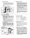
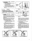
a. Install the Inner:Guide Plate over the bar
....... mounting studs. Figure 3,
NOTE: Be sure the Inner Guide Plate curves
or flanges toward the saw frame away from
the Guide Bar. Figure 4.
b. Mount the Guide Bar with the slotted end
over the bar mounting studs. Figure 5.
NOTE: Be sure the Guide Bar is positioned
with the round hole below the large slot.
INNER GUIDE
PLATE
Figure 3
Figure 4
c u'c"1
:-;1 ,
Figure 5
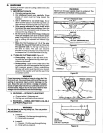
clamp over the mounting studs arid fitting
.the baradjusting pin into the round.hole
in the Guide Bar. Figure 8.
k. Replace the Bar Mounting Nuts and tighten
finger tight only.
NOTE: The Bar Clamp nuts must be slightly
loose to tension the chain correctly,
I, Follow "Chain Tension, •instructions,
page 8.
Figure 6
ADJUSTING PIN HOLE
Figure 7
BAR ADJUSTING PIN
6 6
Figure 8
7