


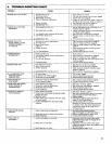

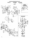

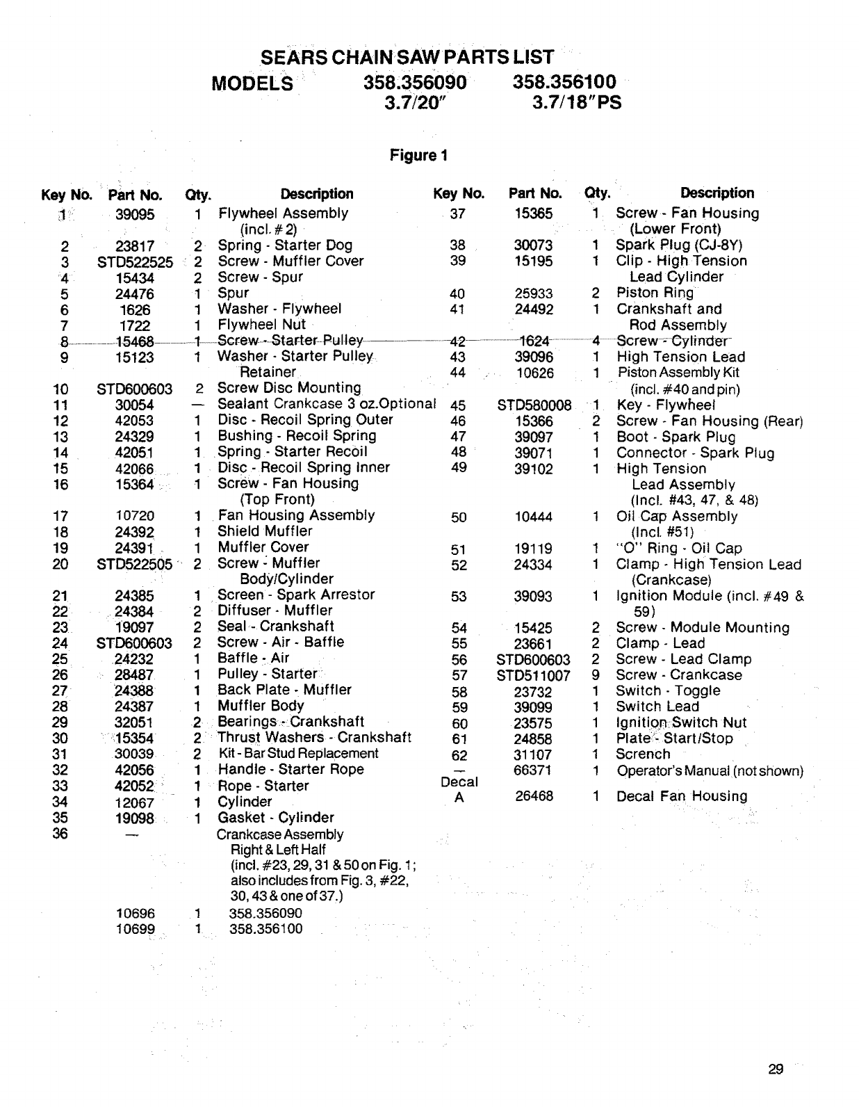
SEARS CHAINSAWPARTS LIST
MODELS 358:356090 358.356100
3.7/20" 3.7/18"PS
2
3
,41
5
6
7
Part No. Qty.
39095 1
23817 2
STD522525 2
15434 2
24476 1
1626 1
1722 1
9 15123
10 STD600603
11 30054
12 42053
13 24329
14 42051
15 42066 .......
16 15364:.
17
18
19
2O
21
22
23
24
25
26
27
28
29
30
31
32
33
34
35
36
10720
24392
24391 -
STD522505 _
24385
24384
1'9097
STD600603
24232
_ 28487
24388
24387
32051
_:_!5354
30039
42056
42052: i
12067
19098 _.
10696
10699
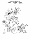
Figure 1
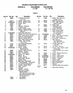
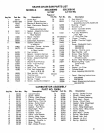
Description Key No. Part No.
Flywheel Assembly 37 15365
(incl. # 2)
Spring - Starter Dog 38 30073
Screw- Muffler Cover 39 15195
Screw - Spur
Spur 40 25933
Washer- Flywheel 4t 24492
Flywheel Nut
1 Washer- Starter Pulley.
Retainer
2 Screw Disc Mounting
Sealant Crankcase 3 oz.Optionai
1 Disc - Recoil Spring Outer
1 Bushing - Recoil Spring
1 .Spring- Starter Recoil
1 Disc-Recoil Spring Inner
1 Screw- Fan Housing
(Top Front)
1 . Fan Housing Assembly
1 Shield Muffler
1 Muffler Cover
2 Screw- Muffler
Body/Cylinder
1 Screen - Spark Arrestor
2 Diffuser- Muffler
2 Seal- Crankshaft
2 Screw - Air- Baffle
1 Baffle ;Air
1 Pulley-Starter
1 Back Plate - Muffler
1 Muffler Body
2 Bearings Crankshaft
2 Thrus t Washers- Crankshaft
2 Kit- Bar Stud Replacement
1 Handle- Starter Rope
1 Rope- Starter
1 Cylinder
1 Gasket- Cylinder
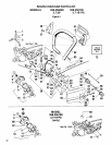
Crankcase Assembly
Right & Left Half
(incl. #23, 29, 31 & 50 on Fig. 1;
also includes from Fig. 3, #22,
30, 43 & one of 37.)
1 358.356090
1 358.356100
43 39096
44 _ 10626
45 STD580008
46 15366
47 39097
48 39071
49 39102
50 10444
51 19119
52 24334
53 39093
54 15425
55 23661
56 STD600603
57 STD511007
58 23732
59 39099
6O 23575
61 24858
62 31107
66371
Decal
A 26468
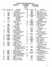
Qty. IDescdption
1 Screw- Fan Housing
(Lower Front)
1 Spark Plug (CJ-8Y)
1 Clip- High Tension
Lead Cylinder
2 Piston Ring
1 Crankshaft and
Rod Assembly
1 High Tension Lead
1 Piston Assembly Kit
(incl. #40 and pin)
1 Key- Flywheel
Screw- Fan Housing (Rear)
1 Boot - Spark Plug
1 Connector - Spark Plug
1 High Tension
Lead Assembly
(Incl. #43, 47, & 48)
1 Oil Cap Assembly
(Incl. #51)
! "O" Ring - Oil Cap
1 Clamp- High Tension Lead
(Crankcase)
1 Ignition Module (incl. #49 &
59)
2 Screw- Module Mounting
2 Clamp- Lead
2 Screw - Lead Clamp
9 Screw- Crankcase
1 Switch - Toggle
1 Switch Lead
1 Ignitior_ Switch Nut
1 Plate:': Start/Stop
1 Scrench
1 Operator's Manual (not shown)
1 Decal Fan Housing
29 ¸