


13
DESCRIPTION cont.
12
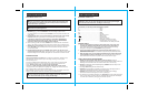
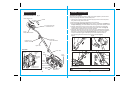
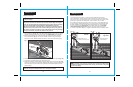
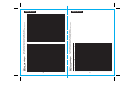
ASSEMBLY & ADJUSTMENTS
The handle comes packaged in sections, which are connected together by internal coated
wiring running through the middle of all the handle pieces.
1. Carefully remove packing material and plastic wrapping around tool and handle pieces,
being careful to keep pieces connected.
2. Remove the Knobs and Curved Head Bolts from the plastic bag.
3. Remove the black plastic tube coating from the piece of wire between the Handle and
the Upper Tube (Fig. 1). This will enable the bolt to fit through the smaller diameter Handle.
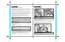
4. Slide the Handle down into the end of the Upper Tube so the holes line up (Fig. 3a).
Carefully insert bolt, being careful to avoid covered wire inside handle shaft (Fig. 3b).
Fasten together by tightening Knob onto Curved Head Bolt.
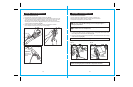
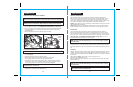
5. Slide Upper Tube down into Lower Tube so that holes line up. Do not remove the black
plastic tube coating from the wire at this connection.There are two positions available for
adjustment to your preferred height (Fig.4a). NOTE: When you first insert the bolt,
it may be necessary to wiggle it carefully to get it past the coated wire inside the
Tube. Fasten together with second Knob and Curved Head Bolt (Fig.4b).
NOTE: Be sure the wire cable moves smoothly down into the Lower Handle Tube
while assembling.
ATTACHING THE HANDLE
Fig. 3b Fig. 3a
Fig. 4a Fig. 4b
CAUTION:
NEVER use a sharp object to move coated wires out of the way.
!
Fig. 2
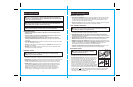
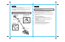
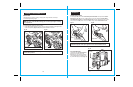
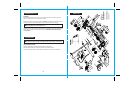
KNOW YOUR EDGER cont.
Power Switch Lever
Handle
Power
Safety Lock-Off Switch
Knobs with
Curved Head Bolts
Extension Cord
Retainer with Hook
2-Prong Power Plug
for extension cord
Upper Tube
Lower Tube
Rear
Wheels
Front
Wheel
Blade
Guard
Blade Guard
Release Lever
Screw to loosen
Blade Guard
Edge Guide
Blade
Cut Line
Indicator
Front View
Cutting Depth Knob
with Release Lever
Edge Guide
Adjustment
Lever
Motor Air
Vents
Blade