


Assembly - 29
ASSEMBLY
Assembly
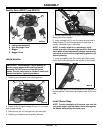
Identify Parts (SP6211 and SP6213)
A - Lawnmower Assembly
B - Side Discharge Chute
C-Bagger
D-BaggerChute
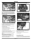
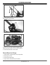
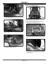
Unfold Handles
1. Carefully remove mower from shipping carton.
2. Loosen knob (A) approximately 25 mm (1 in.) on each
side of upper handle.
3. Remove knob (B) and carriage bolt from each side.
4. Carefully pull folded handle assembly rearward.
5. Rotate slotted bracket (C) to match a desirable height
setting with hole in handle.
6. Install carriage bolt (D) from the inside through hole in
slottedbracket(C)andthroughhandleoneachsideof
handle. Use same hole on each side.
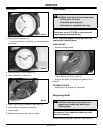
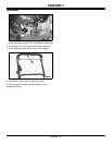
NOTE: If handle height is not satisfactory, move
handle to another hole and height position. Bolts must
travel within slotted adjustment brackets and come to
rest within one of the three height setting positions (E)
before tightening.
7. Install and tighten knob (B) on each bolt. Both handle
knobs should be positioned on the outside of the handles.
8. Pivot upper portion of handle assembly to a straight and
aligning position. Hold handle and tighten knob (A) on each
side.
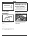
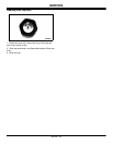
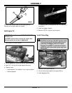
Install Starter Rope
NOTE: To make installation of the starter rope onto the
rope guide easier, hold the blade control lever against
the handle while pulling the starter rope.
IMPORTANT: Avoid damage! Prevent damage to
mower control cables when installing handle
assembly. DO NOT pinch or crimp the control
cables. Control cables must be inside of handle and
unrestricted before tightening hardware.
A
MX1564
B
C
D
MX1565
A
A
B
B
C
D
E
B
M88835
A
M92146