


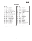


4
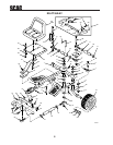
21. Mount the seat onto the seat plate. Place the
(4) four 3/8" flat washers between the seat
and plate. Secure using (4) four 5/16-18 x 3/
4" bolts and (4) four 5/16" lock washers.
22. Mount the seat and seat plate to the seat
spring using (2) two 3/8-16 x 1" bolts and
(2) two 3/8" lock washers.
23. Attach the arm rests to the seat back and use
set screws to adjust arm rests until they are
horizontal.
-Note-
A final adjustment may be required on the
tie rods for the sulky wheels to be aligned
straight with the SWZ machine and to have
proper toe-in adjustment. To adjust the tie
rods, loosen the two jam nuts and turn the
tie rod tube to lengthen or shorten the tie
rod. Retighten jam nuts.
24. The two sulky wheels should have a 1/16"
toe-in adjustment. To make this adjustment,
adjust the two wheel tie rods.
25. Start the engine and drive the mower with
the sulky attached. If the sulky does not
track straight behind the mower, you must
adjust the streeing rod so that the wheels are
even with the mower.
-Note-
For operator comfort the handles on the
SWZ should be raised to the highest
position. Refer to the SWZ's technical
manual for this adjustment.
-Note-
To move the sulky when not attached to the
mower, you must lock the wheels in a
forward position. The wheels can be
locked in the forward position by inserting
the ring pin through the holes in the sulky
frame and the steering bellcrank.
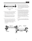
16. On the steering tie rod, adjust the ball joints
on the tie rod so that you will get 32-1/2”
distance between the center to center holes
on the ball joints. (See figure 3)
17. Tighten the jam nuts on the ball joints
against the tie rod ends to prevent turning of
the ball joints on the tie rods.
18. Connect the 1/2 x 1/2-20 end of the steering
tie rod to the small lever on the steering
bellcrank. Place a 1/2" spacer between the
ball joint and steering lever and secure using
a 1/2-13 x 2" bolt and a 1/2-13 elastic stop
nut.
19. Mount the 5/8 x 1/2-20 end of the tie rod to
the pin on the hitch bracket and secure with
the small quick pin.
20. Mount the seat spring and reinforcement seat
spring above the sulky frame and mount the
lower support plate below the sulky frame.
Secure using the (2) two 7/16-14 x 4" bolts,
(2) two 7/16" flat washer and (2) two 7/16-
14 elastic stop nuts.
-Note-
There are extra bolt holes to choose from
when mounting the seat spring to the sulky
frame and mounting the seat and seat plate
to the seat spring. Choose the ones that
will provide the most comfort for the
individual users.
32 1/2"
STEERING TIE ROD ADJUSTMENT
SC504G
Figure 3