


3
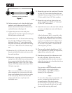
13. Bolt one end of the other wheel tie rod
below the lever on the right wheel spindle.
Place a 1/2" ball joint spacer between the ball
joint and wheel spindle lever. Secure using a
1/2-13 x 2" bolt and a 1/2-13 elastic stop
nut. (See figure 2)
14. Place the other end of the tie rod coming
from the left wheel above the larger lever of
the steering bellcrank located in the center of
the sulky frame. Place the other end of the
tie rod coming from the right wheel below
the larger lever of the steering bellcrank.
Place (2) two 1/2" ball joint spacers between
the (2) two ball joints and the steering
bellcrank lever. Secure using a 1/2-13 x 3
1/4" bolt and a 1/2-13 elastic stop nut. (See
figure 2)
15. Screw the remaining LH and RH threaded
1/2-20 jam nuts onto the remaining two ball
joints.
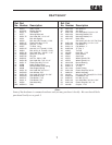
Figure 1
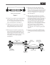
10. On the (2) two wheel tie rods, adjust the ball
joints on the tie rods so that you will get
12- 7/8” distance between the center of the
holes on the ball joints. (See figure1)
11. Tighten the (4) four jam nuts on the ball
joints against the tie rod ends to prevent
turning of the ball joints on the tie rods.
12. Bolt one end of a wheel tie rod above the
lever on the left wheel spindle. Place a 1/2"
ball joint spacer between the ball joint and
wheel spindle lever. Secure using a 1/2-13 x
2" bolt and a 1/2-13 elastic stop nut.
(See figure 2)
12 7/8"
WHEEL TIE ROD ADJUSTMENT
SC502G
Figure 2
SC503G
WHEEL TIE ROD
WHEEL TIE ROD
1/2" SPACER
1/2" SPACER
LEFT WHEEL
SPINDLE LEVER
RIGHT WHEEL
SPINDLE LEVER
CENTER
STEERING LEVER