


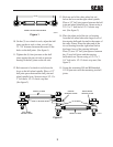


2
ASSEMBLY INSTRUCTIONS
-Note-
Before assembling and connecting this
accessory to your machine, turn the engine
off, remove the key, and remove the spark
plug wire from the engine.
1. Remove all crating and packing materials.
Lay out the mounting hardware according to
the “where used” list on page 5.
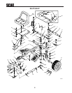
2. Bolt the hitch bracket onto the rear of the
engine deck using (3) three 3/8-16 x 1-1/4"
bolts and (3) three 3/8-16 elastic stop nuts.
The bolts must be installed from the inside
facing out.
-Note-
If you are mounting the hitch bracket to an
older machine with only two holes on
the rear of the engine deck, you may use the
hitch bracket to locate the third hole.
Bolt the hitch bracket to the existing two
holes and mark the third hole using a
center punch. Unbolt the hitch bracket and
drill a 13/32" hole at the mark for the
third hole. You are now ready to mount the
hitch bracket.
3. Mount the hitch ball onto the hitch bracket
using the 3/4" lock washer and the 3/4"-16
hex nut.
4. Mount the wheel assemblies onto the wheel
spindles. Place the 1" wheel spacers onto the
wheel spindles, and install the "E" clip on to
each of the wheel spindles.
-Note-
There will be more wheel spacers in the
hardware package than you will use. Install
the appropriate sized wheel spacers onto the
wheel spindle to remove the back and forth
movement of the wheel assemblies with the
“E” clip installed.
5. Mount the sulky frame on the hitch ball and
secure in place by pushing down the locking
lever on the coupler.
-Note-
When performing steps 5 through 8 keep in
mind that the (3) three tie rods will have
one end that has RH threads and one end
that has LH threads.
Included in the hardware package are:
l (3) three LH threaded 1/2 x 1/2-20
ball joints.
l (3) three LH threaded 1/2-20 jam
nuts.
l (2) two RH threaded 1/2 x 1/2-20
ball joints.
l (1) one RH threaded 5/8 x 1/2-20
ball joint.
l (3) three RH threaded 1/2-20 jam
nuts.
6. Screw (2) two LH threaded 1/2-20 jam nuts
onto (2) two LH threaded 1/2 x 1/2-20 ball
joints.
7. Screw (2) two RH threaded 1/2-20 jam nuts
onto the (2) two RH threaded 1/2 x 1/2-20
ball joints.
8. There are three tie rods included in the sulky
assembly. The two shorter ones are the
wheel tie rods and the longer one is the
steering tie rod.
9. Screw the (2) two LH 1/2 x 1/2-20 ball
joints with jam nuts into the LH threaded
ends of the wheel tie rods. Screw the RH
1/2 x 1/2-20 ball joints with jam nuts into the
other wheel tie rod ends.