


Section 6
25
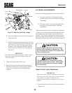
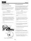
3. If the adjustments are okay and you need to adjust
the neutral linkages, proceed with the Neutral
Adjustment procedures. If the speed control requires
adjustment, adjust as follows:
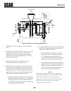
A. Loosen both jam nuts (A & B, Figure 6-6) on the
adjusting rod (C).
-NOTE-
All turnbuckles have a left hand threaded nut and a
right hand threaded nut. The left hand nut is located
next to the ball joint that has a groove etched into its
outer surface.
B. Using a wrench on the hex portion of the
adjusting rod, turn the adjusting rod (C) in the
required direction to move the bellcrank against
the bushing. When the correct adjustment is
obtained, tighten the two jam nuts (A & B).
C. Proceed with the Neutral Adjustment.
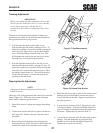
Neutral Adjustment
1. Locate the left hand speed control lever. Using a
ruler, check the distance between the ball joint and
the center of the pivot point of the lever (Figure 6-6).
The dimension must be 4-1/2 inches or be in the
center of the slot. If correct, proceed to step 2. If
incorrect, loosen the lock nut securing the ball joint to
the lever and relocate the ball joint to the correct
position.
2. Loosen the two jam nuts (D & E, Figure 6-6) on the
right side neutral linkage and the two jam nuts
(F & G) on left side neutral linkage.
3. With a person seated in the operator’s seat, disengage
the parking brake and start the mower’s engine.
4. SLOWLY rotate the turnbuckle (H, Figure 6-6) on
the right side until the mower starts to creep forward.
When the mower starts to creep forward, stop the
movement and turn the turnbuckle back 1/2 turn or
three flats (Figure 6-6).
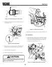
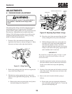
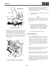
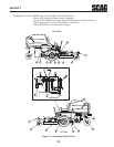
Figure 6-4 Neutral Position
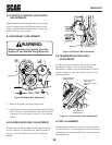
2. Check that the speed control bellcrank (Figure 6-5) is
touching the bushing on the frame and that the block
on the speed control lever has engaged the neutral
switch (Figure 6-4). The switch button should not be
fully compressed. If the switch is engaged, but the
bellcrank is not touching the bushing, full speed will
not be obtainable.
Resting On
Bushing
Figure 6-5 Bellcrank Touching Bushing
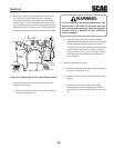
Bracket Against
Pressure Switch
Neutral Interlock Switch