


Section 6
23
ADJUSTMENTS
6.1 PARKING BRAKE ADJUSTMENT
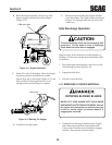
WARNING:
Do not operate the mower if the parking brake is
not operable. Possible severe injury could
result.
The parking brake linkage should be adjusted whenever
the parking brake lever is placed in the “ENGAGE”
position and the parking brake will not prevent the mower
from moving. Adjustments can be made to the brake
linkage. If the following procedures do not allow you to
engage the parking brake properly, contact your Scag
dealer for further brake adjustments.
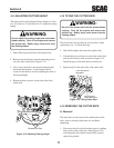
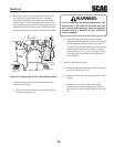
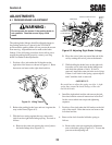
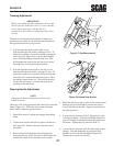
1. Position a floor jack under the lift bracket on the
right side of the tractor as shown in Figure 6-1. Raise
the tractor and remove the right wheel and tire.
Figure 6-1 Lifting Tractor
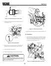
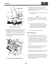
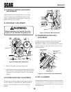
2. Release the parking brake lever and rest it against the
stop on the frame (Figure 6-2).
3. With the lever resting against the stop, remove the
slack from the right brake linkage spring. Proceed as
follows:
A. Remove the cotter pin securing the swivel joint to
the brake linkage arm (Figure 6-2).
Remove Cotter Pin Here
Brake Rod
Parking
Brake
Lever
Swivel
Joint
Hold Brake Lever
In This Direction
Figure 6-2 Adjusting Right Brake Linkage
B. Move the swivel joint out toward the end of the
rod by rotating the swivel joint on the threads.
C. While holding the brake lever on the right axle,
insert the swivel joint in the brake linkage arm
and check the amount of slack. If slack is
removed, install the cotter pin in the swivel joint.
If there is still slack in the spring, repeat steps B
and C until the slack is removed.
-IMPORTANT-
Be careful not to adjust the spring too tight. A tight
spring may actuate the brake linkage on the axle
and set the brake.
4. Install the right wheel and tire and remove the jack.
See wheel and tire removal instructions in Section 7
for the correct wheel nut torque and tightening
sequence.
5. Position a floor jack under the lift bracket on the left
side of the tractor. Raise the tractor and remove the
left wheel and tire.
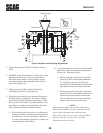
6. Remove the slack from the left brake spring as
follows:
A. Remove the cotter pin securing the adjustment
arm to the brake spring (Figure 6-3). Loosen the
jam nut on the adjusting rod.