


11
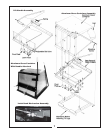
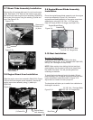
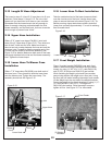
2-11 Blower Cone Installation
Thread (1) 5/16”-18 jam nut P#(K0120) onto each end of
(2) 5/16”-18 x 2-1/2” HHCS P#(K0125). Now partially
thread the bolts into each of the two tabs located on the
blower housing. Place blower cone so the two tabs line up
with the bolts then tighten completely. See Figure 2-11.
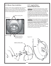
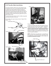
2-12 Impeller Blade
Removal/Replacement
To Remove:
To Replace
First remove the center bolt (#1), washer
(#2) and spacer (#3) from the taper-lock bushing (#5).
See Figure 2-12. Next remove the (2) 1/4”-20 bolts (#4)
and place them into the threaded holes of the taper-lock
bushing (next to the holes they were removed from).
Gradually thread each bolt evenly into the taper-lock
bushing, forcing the blade to break-away from the taper-
lock bushing. If the impeller will not move, hit the base of
the impeller, between each vein, with a hammer, then try
again.
Place impeller blade over the engine shaft.
Slide the taper-lock bushing on to the engine shaft and
into the impeller blade, aligning the holes
of the taper-lock bushing to the threaded holes of the
impeller blade. Fasten by using (2) 1/4”-20 HHCS
Grade #8 bolts, (1) spacer washer and (1) HHCS bolt w/
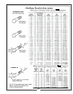
washer. Torque to the proper specifications in the torque
chart on the back of this manual. Next, rotate the
impeller blade to insure that the blade is clear of contact
on all sides of the blower housing.
Figure 2-12.
:
non-threaded
Figure 2-11.
(2) 5/16”-18 x 2-1/2”
All Thread HHCS And
(2) 5/16” Jam Nuts
Blower Cone
Blower Housing Tabs
IMPELLER BLADE
1
2
3
4
5