


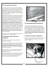
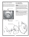

2-9 Engine/Blower/Blade Assembly
Installation
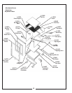
Place the engine/blower/blade assembly onto the engine
mount arm assembly (Figure 2-9). Secure the
engine/blower/blade assembly to the engine mount arm
assembly by using (4) 5/16"-18 x 1-1/2" hex bolts
P#(K1157) and (4) 5/16"-18 flange nuts P#(K1178).
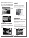
To mount the boot plate P#(B0309) to the boot
P#(E0012) use (2) 3/8”-16 x 1” carriage bolts P#(K1182)
and (2) 3/8”-16 flange nuts P#(K1215).
Make certain when bolting the boot and boot
plate together, that the head of the bolt is placed from
the inside of the boot. This will prevent grass from
collecting on the bolts.
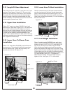
To install the boot plate and boot to the deck, lift boot
plate assembly to a 45 degree angle and slide bent tabs
under the deflector shield as shown in Figure 2-10.
Adjust boot as needed to insure proper fit.
2-10 Boot Installation
Mounting The Boot Plate
NOTE:
The boot plate will allow you to switch from collection to
discharge in seconds.
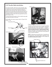
2-7 Mount Tube Assembly Installation
Remove the (4) carriage bolts and (4) nuts from the rear
plate. See Figure 2-7a. Remove the mower’s rear plate
and secure the outer engine mount assembly P#(A0416)
to the rear of the mower using the existing (4) bolts and
nuts. See Figure 2-7b.
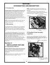
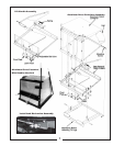
2-8 Engine Mount Arm Installation
Slide the engine mount arm assembly P#(A0318) (Figure
2-8) into the outer engine mount assembly. Secure the
engine mount arm assembly using (1) detent pin
P#(J0248).
Figure 2-10.
Figure 2-8.
Figure 2-9.
10
(4) 5/16"-18 x 1-1/2" Bolts
(4) 5/16"-18 Flange Nuts
Boot
Boot Plate
(2) 3/8”-16 x 1 Carriage Bolts
(2) 3/8”-16 Flange Nuts
(1) Detent Pin
Engine/Blower/Blade
Assembly
Engine Mount
Arm Assembly
Figure 2-7a.
Remove
Plate
Remove (4)
Bolts And
(4) Nuts
Figure 2-7b.
Outer Engine
Mount Assy.