3
ASSEMBLY INSTRUCTIONS
■ TOOL LIST
• Screwdriver (Phillips or Standard)
• Allen wrench 4mm
• 10mm wrench
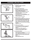
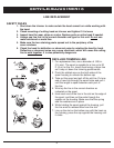
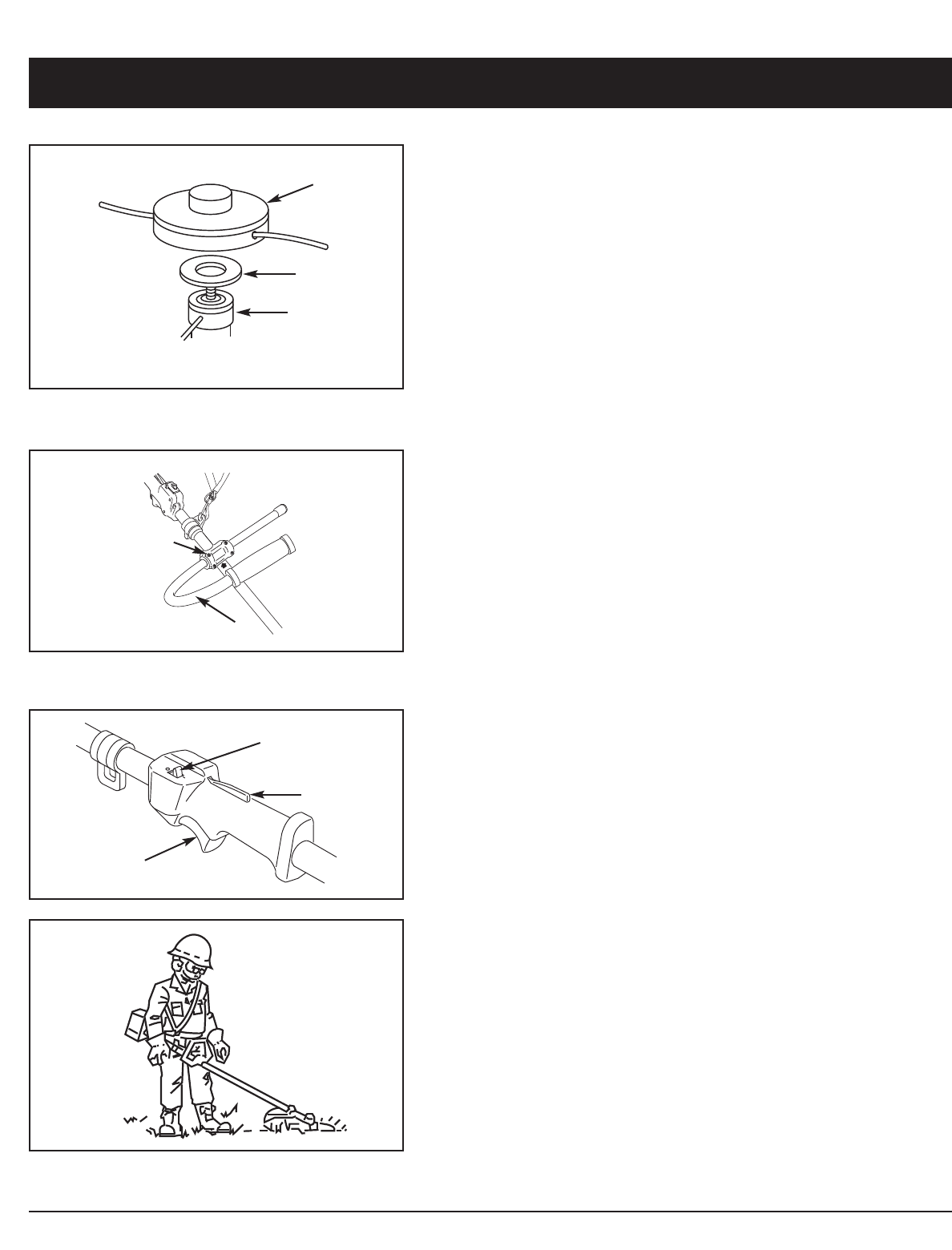
■ INSTALLING CUTTING HEAD
• See page 9 for blade removal instructions.
• Make sure debris shield with line cut off is
properly installed. See next page.
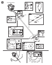
• Lock gear box (3) by inserting a 1/8 in. (4 mm)
allen wrench or pin thru hole and finding
corresponding notch.
• Install splined washer (2) flat side out.
• To install head (1), turn counterclockwise. Hand-
tighten head securely.
• To remove head, turn clockwise
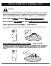
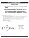
■ INSTALLING THE “J” HANDLE
• Install the clamp assembly on the shaft tube. The
top of the clamp should touch the arrow on the
tube. Leave the screws and nuts slightly loose.
• Place J handle in clamp as shown- The J shape
goes on right side of unit. Position the handle
until the arrow on the handle touches the edge of
the clamp.
• Tighten the screws.
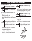
■ THROTTLE–KILL SWITCH
• To accelerate unit hold down lever (3) with the
palm of the RIGHT hand. Then squeeze the
trigger (2).
• To return to idle. Release trigger (2).
• To stop the unit push switch (1) forward.
• To start the unit pull switch (1) back.
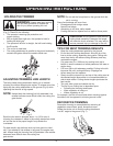
■ SHOULDER HARNESS
• Place the strap over your left shoulder and attach
clip to clamp eye on shaft tube.
• Loosen clamp screw and slide clamp up or down
until unit balances with head just touching the
ground.
• Tighten screw.
• Notice quick release feature.
1
2
1
2
3
1
2
3


