


7 — English
ASSEMBLY
WARNING:
To prevent accidental starting that could cause serious
personal injury, always disconnect the engine spark plug
wire from the spark plug when assembling parts.
WARNING:
Be certain all knobs are fully tightened before operating
equipment; check them periodically for tightness during
use to avoid serious personal injury.
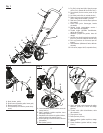
INSTALLING THE PRO CUT II
™
STRING HEAD/
SHAFT ASSEMBLY TO THE TRIMMER POWER
HEAD/WHEEL ASSEMBLY
See Figure 2.
The Pro Cut II
™
string head/shaft assembly connects to the
trimmer power head/wheel assembly by means of a coupler
device.
Loosen the knob on the coupler of the power head shaft
and remove the end cap from the string head/shaft
assembly.
Push in the button located on the string head shaft. Align
the button with the guide recess on the power head coupler
and slide the two shafts together. Rotate the string head
shaft until the button locks into the positioning hole.
NOTE: If the button does not release completely in the
positioning hole, the shafts are not locked into place.
Slightly rotate from side to side until the button is locked
into place.
Tighten the knob securely.
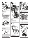
INSTALLING LOWER HANDLEBAR
See Figure 3.
Remove the lower handlebar knobs and bolts from the
hardware bag.
Place the lower handlebar into the openings on the trimmer
power head/wheel assembly as shown.
Insert the bolts through the holes in the handlebar and
frame.
Install the lower handlebar knobs and tighten securely.
INSTALLING UPPER HANDLEBAR
See Figure 4.
Remove two handlebar knobs and bolts from the hardware
bag.
Position upper handlebar onto lower handlebar.
Insert bolts through the holes in the handle and frame.
Slide handlebar knob onto bolt and tighten securely.
Repeat with other side.
NOTE: Do not allow throttle cable to become pinched
when installing the handle or tightening the knobs.
Place the throttle cable in the clip located on the lower
handle. Install the second clip on the upper handle as
shown.
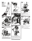
ATTACHING THE GRASS DEFLECTOR
See Figure 5.
WARNING:
The line cutting blade on the grass deflector is sharp.
Avoid contact with the blade. Failure to avoid contact
can result in serious personal injury.
Remove the wing screw from the grass deflector.
Insert the tab on the mounting bracket in the slot on the
grass deflector.
Align the screw hole in the mounting bracket with the
screw hole in the grass deflector.
Insert the wing screw through the mounting bracket and
into the grass deflector.
Tighten the screw securely.
INSTALLING LINE IN PRO CUT II
™
STRING
HEAD
See Figure 6.
Use monofilament line between .095 in. and .105 in. diam-
eter. Use quality monofilament replacement line for best
performance.
Stop the engine and disconnect the spark plug wire.
Gather two of the pre-cut lengths of trimmer line provided
or cut two pieces of trimmer line in 10 in. lengths.
Insert the lines into the slots located on the sides of the
string head. Line should be pushed in until approximately
1 in. protrudes from the holes on the top of the string
head.
Remove old line by pulling it from the holes located on
the top of the string head.
WARNING:
Do not remove screws or disassemble head. If head is
opened, compression springs may fly out toward operator
and result in serious injury.
INSTALLING LINE CARRIER
See Figure 7.
The line carrier snaps onto the lower handlebar on the side
opposite the throttle cable and is used to hold pre-cut pieces
of trimmer line.
NOTE: Do not install the carrier where it could interfere with
the throttle cable or where it could cover any of the warning
icons or labels.
To install line, remove top cap, insert line into carrier, and
replace cap. To remove line for use, pull from open area on
front of carrier.