


16
MAINTENANCE AND REPAIR INSTRUCTIONS
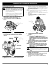
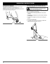
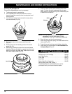
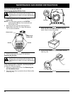
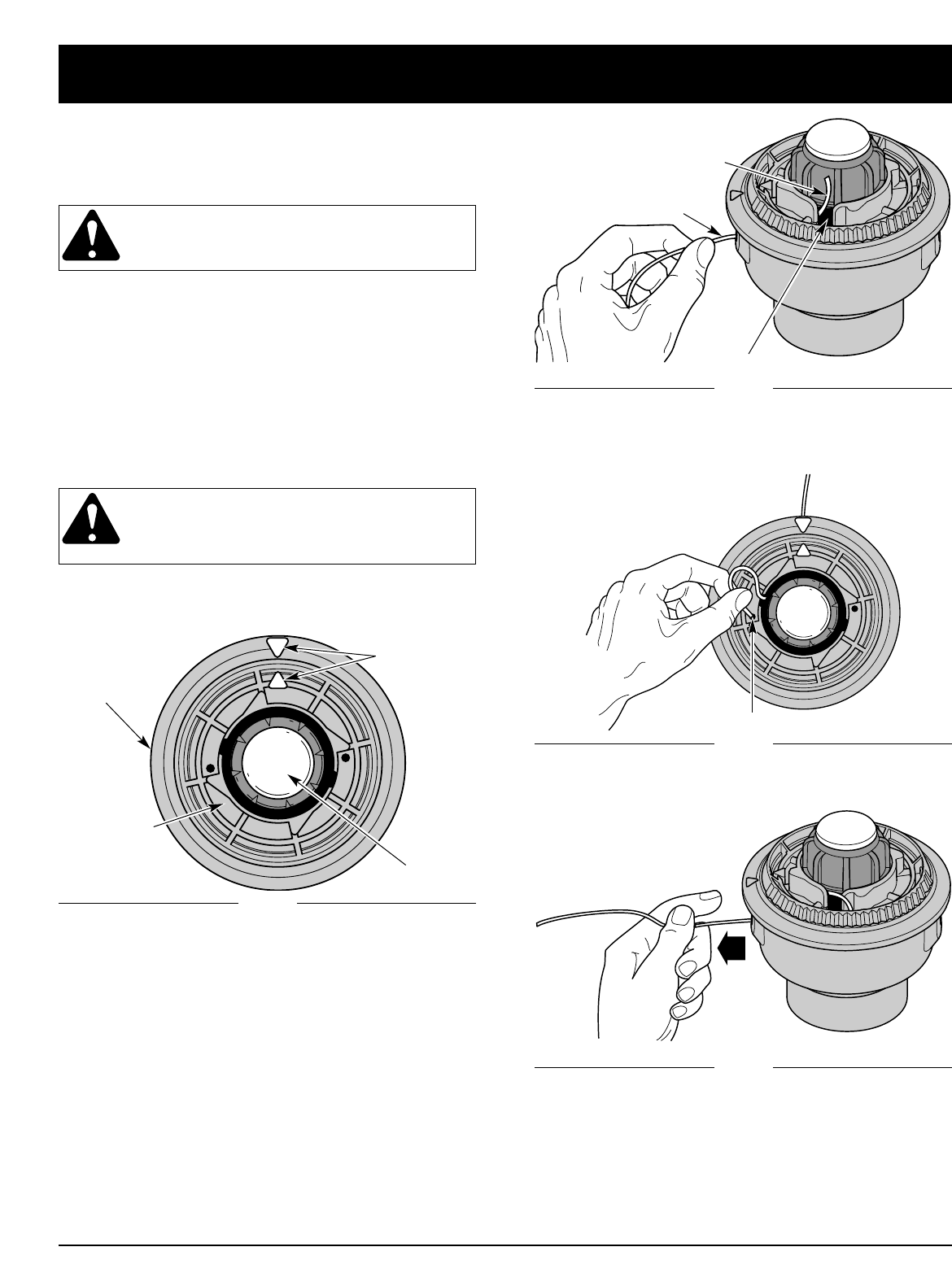
Line Locking Hole
Trimming Line
Line Loading Hole
Eyelet
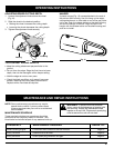
5. Insert the line into the locking hole (Fig. 18). Do not
push the line more than 1/2 inch (12.7 mm.) into the
line locking hole. When inserted correctly the line will
form a small loop (Fig. 18).
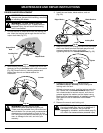
6. Pull the line from the outer spool until the line is tight
against the inner reel (Fig. 19).
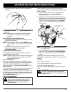
LINE INSTALLATION FOR THE SPEEDSPOOL
®
Always use genuine Ryobi 0.080 in. (2.03 mm.)
replacement line. Larger line may make the engine
overheat or fail.
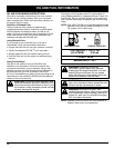
WARNING: Never use metal-reinforced line,
wire, or rope, etc.. These can break off and
become a dangerous projectile.
There are two methods to replace the SpeedSpool
®
trimming line.
• Wind the inner reel with new line
• Install a prewound inner reel
Winding the Inner Reel With New Line
NOTE: It Is unnecessary to remove the bump knob to
install new trimming line.
1. Cut two pieces of 0.080 in. (2.03 mm.) trimming line,
10 feet (3 m.) long.
WARNING: Always use the correct line
length when installing trimming line on the
unit. The line may not release properly if the
line is too long.
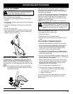
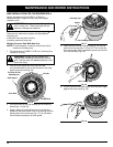
2. Hold the outer spool and turn the inner reel
counterclockwise to line up the arrows on the outer
spool and inner reel (Fig. 16).
3. Pull old line out of the line loading and line locking
holes (Figs. 17 and 18).
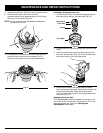
4. Insert a piece of trimming line into one of the two
eyelets in the outer spool. Push it up through the line
loading hole in the inner reel (Fig. 17). Do not bend
the line when inserting it into the eyelet.
Top View Of The
SpeedSpool
®
Outer Spool
Arrows
Inner Reel
Bump Knob
Fig. 16
Fig. 17
Fig. 19
Fig. 18