


OPERATING INSTRUCTIONS
12
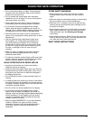
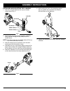
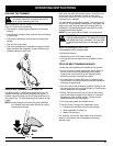
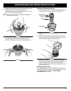
2. While firmly holding the add-on, push it straight into
the Click-Link® coupler (Fig. 8).
NOTE: Aligning the release button with the guide recess
will help installation (Fig. 8).
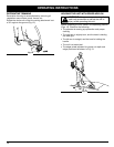
3. Turn the knob clockwise to tighten (Fig. 9).
CAUTION: Lock the release button in the
primary hole and securely tighten the knob
before operating this unit.
OPERATING THE CLICK-LINK
®
SYSTEM
The Click-Link
®
system enables the use of these
optional add-ons.
Blower/Vacuum . . . . . . . . . . . . . . . . . . . . . . . . . . BV720r
Cultivator . . . . . . . . . . . . . . . . . . . . . . . . . . . . . . GC720r
Hedge Trimmer . . . . . . . . . . . . . . . . . . . . . . . . . . HS720r
Snow Thrower . . . . . . . . . . . . . . . . . . . . . . . . . . . ST720r
Straight Shaft Trimmer (SpeedSpool
®
) . . . . . . . . SS725r
Tree Pruner . . . . . . . . . . . . . . . . . . . . . . . . . . . . . TP720r
Turbo Blower . . . . . . . . . . . . . . . . . . . . . . . . . . . . TB720r
WARNING: Read and understand operator’s
manual for add-on prior to operation.
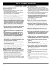
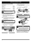
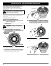
Removing the Cutting Attachment or Add-Ons:
1. Turn the knob counterclockwise to loosen (Fig. 7).
2. Press and hold the release button (Fig. 7.
3. While firmly holding the upper shaft housing, pull the
cutting attachment or add-on straight out of the
Click-Link
®
coupler.
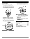
NOTE: The cutting attachment and edger add-on have a
red cap on the end of the shaft housing. Remove
the red cap from the end of the shaft housing
before assembling.
Installing the Cutting Attachment or Add-Ons:
WARNING: To avoid serious personal injury,
shut unit off before removing or installing
add-ons.
NOTE: To make installing or removing the add-on easier,
place the unit on the ground or on a work bench.
1. Turn the knob counterclockwise to loosen (Fig. 7).
Click-Link
®
Coupler
Release Button
Guide
Recess
Knob
Primary Hole
Upper Shaft
Housing
Lower Shaft
Housing
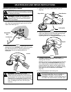
Release Button
90˚ Edging Hole
180˚ Edging
Hole
Knob
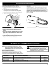
CAUTION: The cutting attachment and
add-ons with the Click-Link
®
system are to
be used in the primary hole unless stated
otherwise in the specific add-ons operator’s
manual. Using the wrong hole could lead to
personal injury, or damage to the unit.
For edging when using the line head cutting attachment
with Click-Link
®
models, lock the release button of the
cutting attachment into the 90° edging hole or the 180°
edging hole (Fig. 9). The edger add-on should be
installed with the release button in the primary hole.
Fig. 7
Fig. 8
Fig. 9
Click-Link
®
Coupler