


MAINTENANCE AND REPAIR INSTRUCTIONS
23
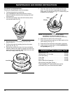
10. If the clearance is not within specification:
a. Turn the adjusting nut using a 5/16 inch (8 mm)
wrench or nut driver (Fig. 42).
• To increase clearance, turn the adjusting nut
counterclockwise.
• To decrease clearance, turn the adjusting nut
clockwise.
b. Recheck both clearances, and adjust as necessary.
11. Reinstall the rocker arm cover using a new gasket.
Torque the screw to 20–30 in•lb (2.2–3.4 N•m).
NOTE: A rocker arm cover gasket, Part # 182099 can be
purchased from your local authorized dealer.
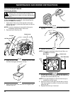
12. Reinstall the engine cover. Check alignment of the
cover before tightening the screws. Tighten screws.
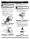
13. Replace the muffler cover. Slip the long tabs on the
muffler cover into the engine cover. Slide the
notches on the side of the muffler cover over the
tabs on the engine cover and snap into place
(Fig. 38).
14. Check the spark plug and reinstall. See Replacing
the Spark Plug.
15. Replace the spark plug wire.
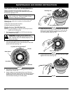
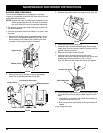
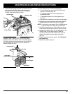
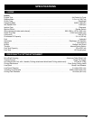
9. Slide the feeler gauge between the rocker arm and
the valve return spring. Measure the clearance
between the valve stem and rocker arm (Fig 42).
Do both intake and exhaust valves.
Adjusting Nuts
Feeler Gauge
Rocker Arms
Gasket
Fig. 42
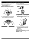
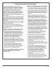
Fig. 43
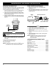
The recommended clearance for both intake and
exhaust is .003 – .006 in. (.076 – 0.152 mm). Use a
standard automotive .005 in. (0.127 mm) feeler gauge.
The feeler gauge should slide between the rocker arm
and valve stem with a slight amount of resistance,
without binding (Fig. 43).
Feeler Gauge
Adjusting Nut
Rocker Arm
.003–.006 in.
(.076–0.152 mm)
Valve Stem