


MAINTENANCE AND REPAIR INSTRUCTIONS
19
INSTALLING A PREWOUND REEL
1. Hold the outer spool with one hand and unscrew the
Bump Knob™ counterclockwise (Fig. 21, Pg 17).
Inspect the bolt inside the Bump Knob™ to make
sure it moves freely. Replace the Bump Knob™
if damaged.
2. Remove the old inner reel from the outer spool
(Fig. 22, Pg. 17).
3. Remove the spring from the old inner reel
(Fig. 22, Pg. 17).
4. Use a clean cloth to clean the spring, shaft, and
inner surface of the outer spool (Fig. 23, Pg. 17).
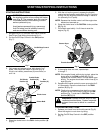
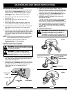
5. Place the spring in the new inner reel. Insert the ends
of the line through the eyelets in the outer spool
(Fig. 28).
6. Place the new inner reel inside the outer spool. Push
the inner reel and outer spool together. While holding
the inner reel and outer spool, grasp the ends and
pull firmly to release the line from the holding slots in
the spool.
NOTE: The spring must be assembled on the inner reel
before reassembling the cutting attachment.
7. Hold the inner reel in place and install the
Bump Knob™ by turning clockwise.
Tighten securely.
EDGER BLADE REPLACEMENT
WARNING:
To avoid serious personal injury,
always wear gloves while handling, removing
or installing the blade.
WARNING: The gear housing gets hot
after long periods of use. To avoid serious
personal injury, do not touch the housing
until it has cooled.
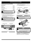
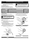
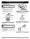
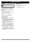
1. Line up the hole in output shaft with the locking rod
slot. Insert the locking rod through the slot into the
output shaft hole (Fig. 29).
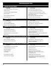
2. While holding the locking rod, loosen the nut on the
blade by turning it clockwise with a 5/8 inch wrench
(Fig. 30). Remove the nut, retaining washer and
blade. Keep the nut and blade retainer for
installation.
Fig. 29
Fig. 31
Fig. 30
Fig. 32
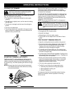
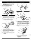
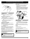
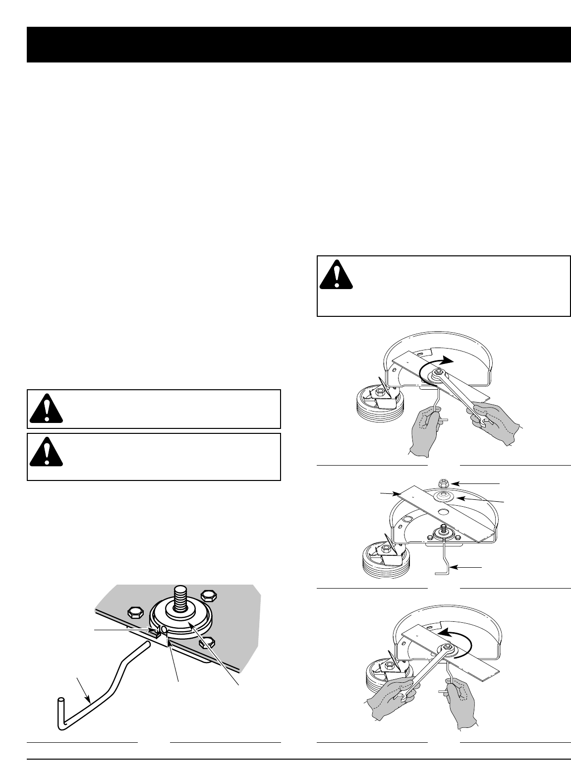
3. Install the new blade, blade retainer, and nut
(Fig. 31). Insert the locking rod through the slot into
the output shaft hole. Make sure that the blade stays
flat and centered against the output shaft while
tightening the lock nut counterclockwise (Fig. 32).
4. If you have a torque wrench, tighten the nut to
325-335 in.•lbs (37-38 N•m), while holding the
locking rod in the slot.
If you do not have a torque wrench, hold the locking
rod in the slot. Rotate the nut counterclockwise
with a 5/8 inch closed-ended or socket wrench, until
the nut presses against the washer and the blade is
snug. Make sure the blade assembly is installed
correctly, then rotate the nut an additional 1/4-1/2
turn (Fig. 32).
5. Remove the locking rod.
WARNING: Verify the blade is flat against
the output shaft after the nut is tightened. If
the blade is off-center, the unit will be
damaged by vibration, and the blade may fly
off, which can cause serious personal injury.
Locking Rod
Locking Rod
Blade Retainer
Lock Nut
Loosen
Tighten
Edger Blade
Output Shaft
Hole
Locking Rod
Slot
Output Shaft