


MAINTENANCE AND REPAIR INSTRUCTIONS
18
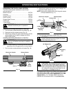
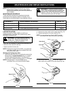
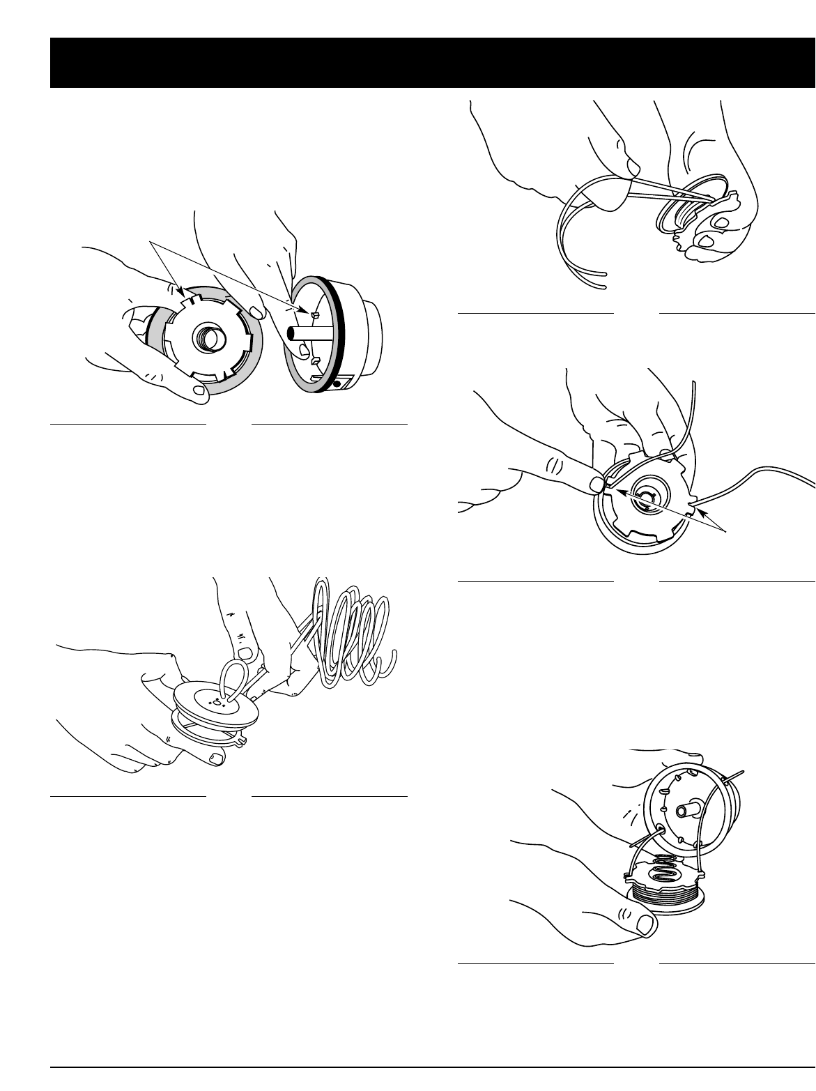
Fig. 26
Fig. 27
Fig. 24
Fig. 25
Fig. 28
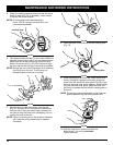
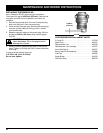
5. Check the indexing teeth on the inner reel and outer
spool for wear (Fig. 24). If necessary, remove burrs
or replace the reel and spool.
NOTE: A cutting attachment head assembly,
Part # 153700 can be purchased from your
local authorized dealer.
Indexing Teeth
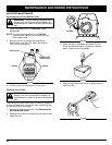
9. Place the spring in the inner reel. Insert the ends of
the line through the eyelets in the outer spool and
place inner reel inside the outer spool (Fig. 28). Push
the inner reel and outer spool together. While holding
the inner reel and outer spool, grasp the ends and
pull firmly to release the line from the holding slots in
the spool.
NOTE: The spring must be assembled on the inner reel
before reassembling the cutting attachment.
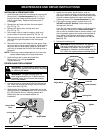
7. Wind the lines in tight even layers, onto the reel
(Fig. 26). Wind the line in the direction indicated on
the inner reel. Place your index finger between the
two lines to stop the lines from overlapping. Do not
overlap the ends of the line.
NOTE: Failure to wind the line in the direction indicated
will cause the cutting attachment to operate
incorrectly.
8. Insert the ends of the line into the two holding slots
(Fig. 27).
6. Take approximately 25 feet (7.6 m) of new 0.080 inch
diameter trimming line, loop it into two equal lengths.
Insert each end of the line through one of the two
holes in the inner reel (Fig. 25). Pull the line through
the inner reel so that the loop is as small as possible.
NOTE: Always use the correct line length when installing
trimming line on the unit. The line may not
release properly if the line is too long.
Holding Slots
10. Hold the inner reel in place and install the
Bump Knob™ by turning clockwise.
Tighten securely.