


STARTING/STOPPING INSTRUCTIONS
12
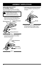
4. Place the choke lever in the FULL choke
position (A) (Fig. 8).
8. If the engine does not start, repeat steps
4 through 7.
NOTE: If the engine floods while trying to
start, place the choke lever in the
RUN position (C). Squeeze the throttle
control. Pull the starter rope briskly.
The engine should start within three (3)
to eight (8) pulls.
9. Squeeze the throttle control to warm up
engine for 5 to 10 seconds. Place the choke
lever in the RUN position (C) (Fig. 8).
NOTE: Choking is unnecessary when starting
a warm engine.
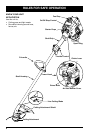
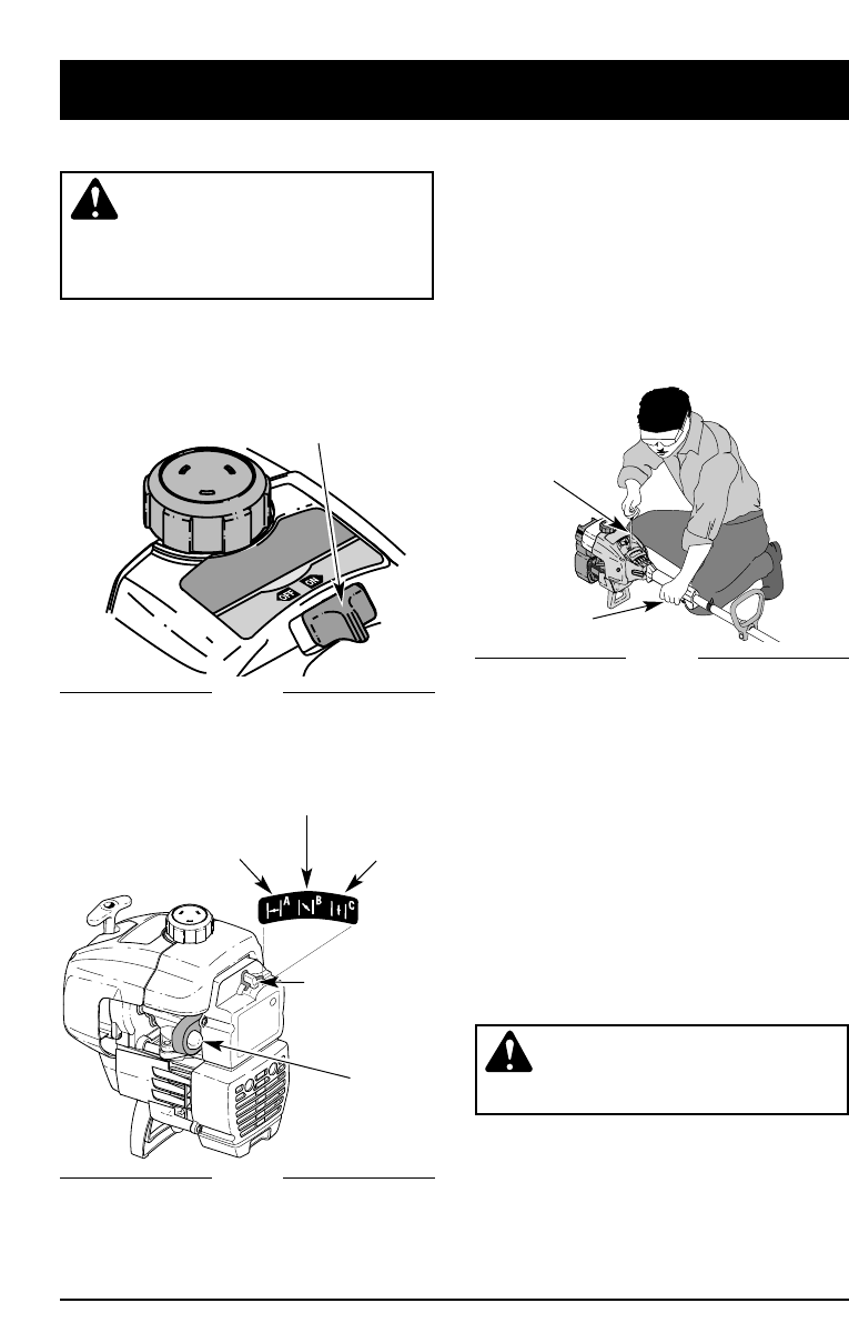
Put the On/Off Stop
Control in the ON position (Fig. 7), and
start in with the choke in the PARTIAL
position (B) (Fig. 8).
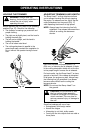
WARNING: Operate this unit only
in a well ventilated area outdoors.
Carbon monoxide exhaust fumes
can be lethal in a confined area.
STOPPING INSTRUCTIONS
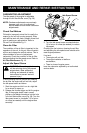
1. Release your hand from the throttle control
(Fig. 9). Allow the engine to cool down
by idling.
2. Put the On/Off Stop Control in the OFF
position (Fig. 7).
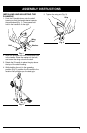
STARTING INSTRUCTIONS
WARNING: Avoid accidental
starting. Be in the starting position
when pulling the starter rope
(Fig. 9). The operator and unit must
be in a stable position while starting
to avoid serious personal injury.
1. Mix gas with oil. Fill fuel tank with fuel/oil
mixture. See Oil and Fuel Mixing
Instructions Pg. 11.
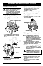
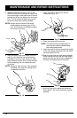
2. Put the On/Off Stop Control in the ON
position (Fig. 7).
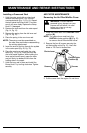
Choke Lever
Full Choke
Position (A)
Run
Position (C)
Partial Choke
Position (B)
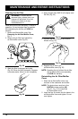
Starter Rope
Throttle Control
ON/OFF STOP CONTROL
3. Fully press and release primer bulb 5 to 7
times. Fuel should be visible in the bulb
(Fig. 8).
5. With the unit on the ground, squeeze the
throttle control and pull starter rope briskly
(Fig. 9). Continue pulling until the engine
sounds as though it wants to run,
(normally 2 to 5 pulls).
NOTE: Squeeze the throttle control until the
engine has started and warmed up.
6. Place the choke lever in the PARTIAL choke
position (B) (Fig. 8).
7. Pull starter rope briskly 1 to 3 times to start
the engine (Fig. 9).
Fig. 7
Fig. 8
Fig. 9
Primer Bulb