


MAINTENANCE AND REPAIR INSTRUCTIONS
18
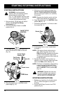
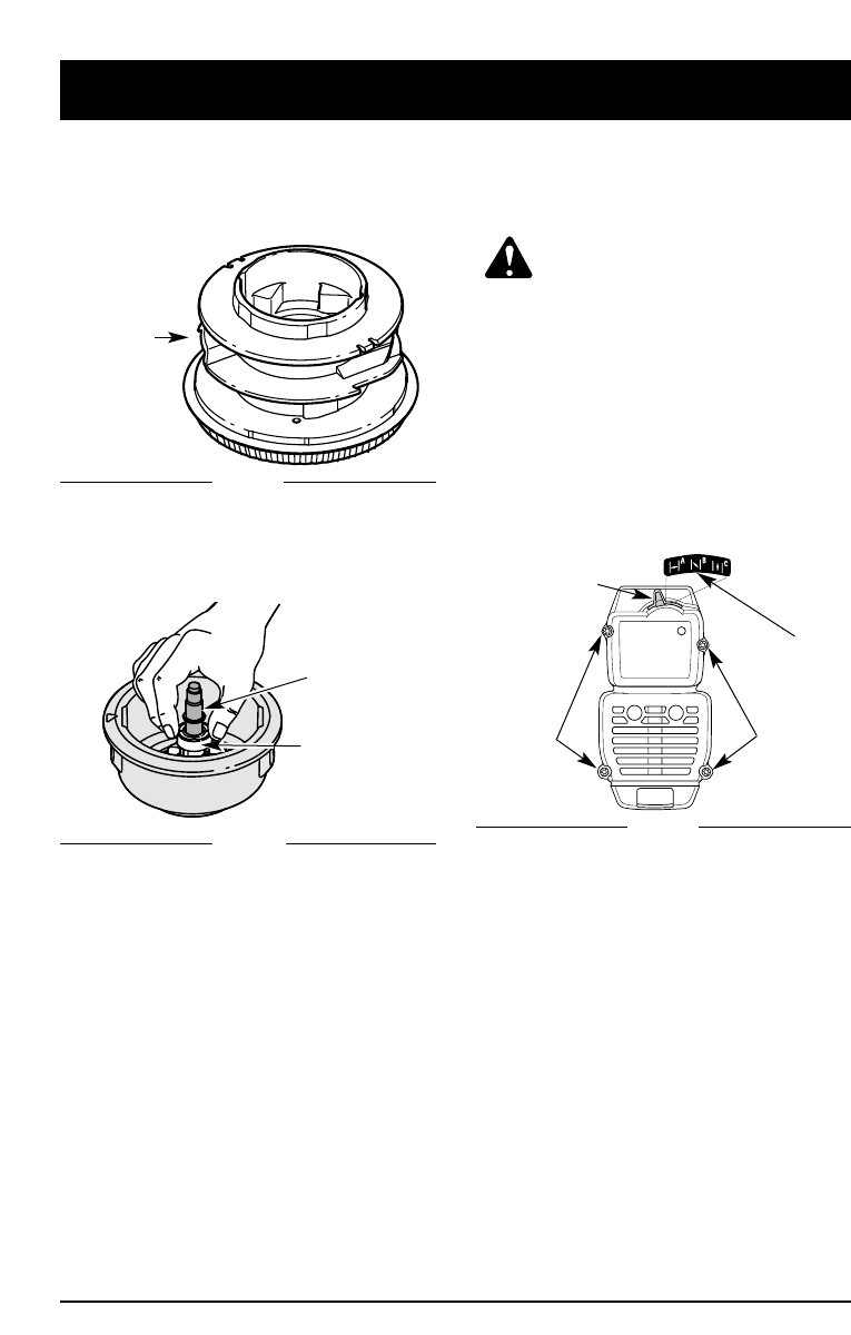
AIR FILTER/MUFFLER COVER
REMOVAL AND INSTALLATION
Removing the Air Filter/Muffler Cover
WARNING: To avoid serious
personal injury, always turn your
trimmer off and allow it to cool
before you clean or do any
maintenance on it.
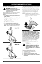
1. Place the choke lever in the PARTIAL choke
position (
B)
.
NOTE: The choke lever must be in the
PARTIAL choke position (B) (Fig. 30)
to remove the Air filter/Muffler cover.
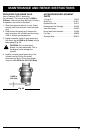
2. Remove the four (4) screws securing the
air
filter
/muffler cover (Fig. 30). Use a flat blade
or #20 Torx bit screwdriver. Pull the cover
from the engine. Do not force.
Choke Lever
Screw
Screw
Partial Choke
Position (B)
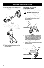
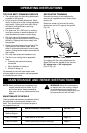
Reinstalling the Airfilter/Muffler Cover
1. Place the Air filter/Muffler cover over
the back of the carburetor and muffler.
NOTE: The choke lever must be in the
PARTIAL choke position (B) (Fig. 30)
to install the Air filter/Muffler cover.
2. Insert the four (4) screws into the holes in the
Air filter/Muffler cover and tighten. Do not
over tighten.
Fig. 30
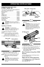
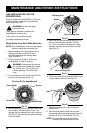
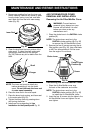
4. Remove any existing line from the inner reel
before cleaning. Remove any debris or grass
from the knob, spring, inner reel, and foam
seal. Wash the inner reel with warm soapy
water (Fig. 28).
Inner Reel
Fig. 28
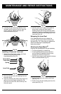
Shaft
Plunger
NOTE: The inner reel must be totally dry
before reinstalling it into the outer
spool. Do not lubricate the inner reel
or outer spool assembly.
6. Place the inner reel in the outer spool.
7. Place the bump knob, spring, and foam seal
in the outer spool (Fig. 25).
8. Tighten the bump knob by pressing down
and turning clockwise.
9. Install new line as described in Line
Installation for the SpeedSpool® Pg. 16.
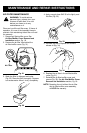
Fig. 29
5. Clean the shaft and the inner surface of the
outer spool. To clean the shaft underneath
the plunger, press down on the plunger
(Fig. 29). Remove any dirt or debris from the
shaft.