


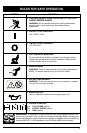

MAINTENANCE AND REPAIR INSTRUCTIONS
15
LINE INSTALLATION
Always use genuine Ryobi 0.080 in. (2.03 mm.)
replacement line. Larger line may make the
engine overheat or fail.
WARNING: Do not use metal
reinforced line.
There are two methods to replace the trimming
line.
• Wind the inner reel with new line
• Install a prewound inner reel
NOTE: Replacement line Part # 610375, or a
prewound reel, Part # 153577 can be
purchased from you local authorized
dealer.
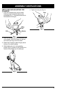
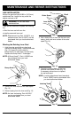
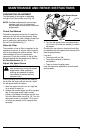
Winding the Existing Inner Reel
1. Hold the outer spool with one hand and
unscrew the Bump Knob™ counterclockwise
(Fig. 12). Inspect the bolt inside the
Bump Knob™ to make sure it moves freely.
Replace the Bump Knob™ if damaged.
NOTE: A Bump Knob™, Part # 153066 can
be purchased from you local
authorized dealer.
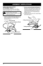
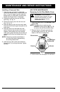
4. Use a clean cloth to clean the the inner reel,
spring, shaft, and inner surface of the outer
spool (Fig. 14).
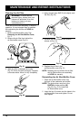
5. Check the indexing teeth on the inner
reel and outer spool for wear (Fig. 15).
If necessary, remove burrs or replace
the reel and spool.
NOTE: A cutting attachment head assembly,
Part # 180879 can be purchased from
you local authorized dealer.
Fig. 12
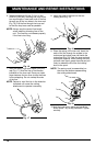
Fig. 13
Fig. 14
Fig. 15
2. Remove the inner reel from the outer spool
(Fig. 13).
3. Remove spring from the inner reel (Fig. 13).
NOTE: An inner reel spring, Part # 610317
can be purchased from you local
authorized dealer.
Inner Reel
Outer Spool
Spring
Indexing Teeth
Bump Knob™
Shaft