


9
2006 RuggedCom Inc. All rights reserved Rev101
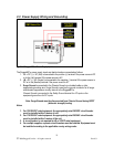
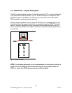
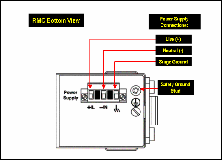
2.3 Power Supply Wiring and Grounding
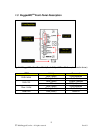
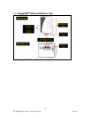
Fig. 2.2.1 RuggedMC
TM
Power Supply Inputs
The RuggedMC
TM
power supply inputs are identical and are connected as follows:
1. +/L = DC (+) / AC (Hot) is connected to the positive (+) terminal if the power source is DC
or to the (Hot) terminal if the power source is AC.
2. -/N = DC (-) / AC (Neutral) is connected to the negative (-) terminal if the power source is
DC or to the (Neutral) terminal if the power source is AC.
3. Surge Ground is connected to the Chassis Ground via a braided cable or other
appropriate grounding wire. Surge Ground is used as the ground conductor for all surge
and transient suppression circuitry internal to the RuggedMC
TM
.
Chassis Ground is connected to the Safety Ground terminal for AC inputs or the
equipment ground bus for DC inputs.
Note: Surge Ground must be disconnected from Chassis Ground during HIPOT
(dielectric strength) testing.
Notes:
1. For 125/250VDC rated equipment: An appropriately rated 300VDC circuit breaker
must be installed within 3 meters of unit.
2. For 110/230VAC rated equipment: An appropriately rated 250VAC circuit breaker
must be installed within 3 meters of the unit
3. A circuit breaker is not required for 48 or 24VDC rated equipment.
4. For multiple supplies, separate circuit breakers must be installed. Equipment must
be installed according to the applicable country wiring codes.