


10
2006 RuggedCom Inc. All rights reserved Rev101
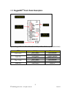
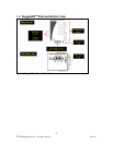
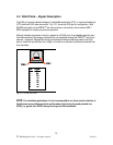
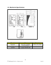
2.4 RJ45 Ports – Signal Description
The RJ45 port accepts standard category 5 unshielded twisted pair (UTP), or screened twisted pair
(STP) cable with RJ45 male connectors. Fig. 2.3.1 shows the RJ45 port pin configuration. Both
RJ45 Ethernet ports on the RMC40
TM
are auto-crossover, auto-polarity, auto-crossover (MDI /
MDIX) equipped, for simple plug-and-play operation.
Although transient suppression circuitry is present on all RJ45 ports, they cannot protect the port
from high-amplitude, high-energy transients that can potentially damage the RMC40
TM
and its link
partners. In general, RuggedCom strongly recommends limiting connections used by the RJ45
ports to those that are less than 3m in length, or limited to environments sufficiently protected from
such transients.
PIN 1
PIN 8
PIN SIGNAL
1 RX+
2 RX-
3 TX+
4 n.c.
5 n.c.
6 TX-
7 n.c.
8 n.c.
PIN 1
PIN 8
PIN SIGNAL
1 RX+
2 RX-
3 TX+
4 n.c.
5 n.c.
6 TX-
7 n.c.
8 n.c.
Fig. 2.3.1 RJ45 Port Pins
NOTE:
For substation applications it is not recommended to use these ports to interface to
field devices across distances which could produce high levels of ground potential rise
(GPR), (i.e. greater than 2500V) during line-to-ground fault conditions.