


Rover Mowers Limited Model 45 Rover Mowers Limited Model 45
ADJUSTMENTS OPERATION
TMTM TMTM
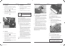
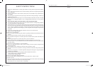
4.4 CUTTING HEIGHT
The cutting height is adjusted with the front roller
adjustmentknob(A)Figure9.
To raise the cutting height, turn the knob clock-
wise. To lower the cutting height, turn the knob
anti-clockwise.
Figure 9. Cutting height adjustment
4.5 CLUTCH
In the unlikely event of clutch slip and loss of pro-
puslion, the clutch operating pressure can be
adjusted.
1. Remove the four retaining screws and wash-
ers securing the clutch cover to the chassis
and lift off the cover. Exposing the drive
shaft, clutch and drive adjuster. Figure 11
2. Loosenthelocknut(C)Figure10.
3. Turnthethreadedadjuster(D)anti-clockwise
two complete turns. Figure 10.
4. Tightenthelocknut(C)andchecktheop-
eration of the clutch.
5. Replace the clutch cover and secure with
four screws and washers.
Figure 10. Clutch adjustment, clutch cover shown
removed.
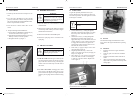
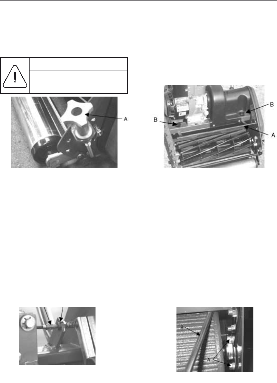
4.6 GRASS DELFECTOR
Depending on the grass cutting conditions, the
angleofthegrassdeectormayneedtobealtered
to direct the cut grass into the catcher.
1. Loosenthethumbscrews(B)eachsideof
the machine Figure 11.
2. Movethedeectorplateeitherforward,to
throw up the cut grass higher and further, or
backwards, to throw the cut grass lower.
3. Re-tightenthethumbscrews(B).Figure11.
Figure 11. Grass deector
4.7 BLADE LEVELLING
1. Placemoweronaatsurface.
2. RemoveGrassdeectorbylooseningthetwo
thumbscrews(B)Figure11.
3. Loosenthethreenuts(A)Figure12onthe
right hand drum bearing housing to allow rear
drum level to be adjusted.
4. Place screw driver underneath and in the
centre of the front roller.
5. Usingarulemeasuretheheightfromtheat
surface to the bottom edge of the bottom blade
on the sole plate at either end of the blade.
6. With a large screw driver in between the
rear roller and the frame from the rear of the
mowerFigure12(B),levertheframeupwards
until the blade is level.
7. Retightenthethreenuts(A)tosecurethe
blade in it’s level position.
5
CAUTION
When setting LOW cut, ensure that the
front roller contacts the ground and not the
bottom blade.
D C
Figure 12. Blade levelling.
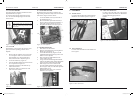
2. CONTROLS
2.1 Throttle control
Located on the right hand arm of the handle bars.
Marked for slow and fast positions. Figure 2.
2.2 Drive clutch lever.
Located on the left hand arm of the handle bars
bars. Figure 3.
2.3 Cutter drive clutch lever.
Located to the left hand side of the engine
protruding out from the shaft cover. Marked for
engaged and disengaged positions.
Figure 4.
Figure 4. Cutter drive clutch lever.
Figure 3. Drive clutch lever.
Figure 2. Throttle control.
2
2892 Reel Mower IMPOSED.indd 5 9/11/2005 9:12:51 AM