


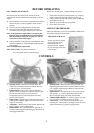

BEFORE OPERATING
FILL CRANKCASE WITH OIL.
The rider mower may be delivered with out oil in the
crankcase. Oil must be added before attempting to start the
engine.
1.
Place machine on level surface. Open the bonnet. Ensure
that the oil plug is securely tightened. Clean around
dipstick.
2.
Unscrew and remove dipstick from oil filler tube.
3.
Insert funnel into filler tube and slowly add oil in
accordance with the engine manufacturer’s direction.
Note: Avoid premature engine failure by ensuring the
funnel is clean so contaminants are not introduced
into the crankcase. Wipe any oil spills so it will not
cause dirt to collect on the engine
4.
Ensure oil level is at the full mark on the dipstick, when
screwed completely in. When finished replace dipstick
and retighten.
Note: See Maintenance Instructions
FILL FUEL TANK – See Safety Instructions.
Use only regular grade or unleaded petrol.
Do not mix oil with petrol. – Engine damage may result.
1. Open bonnet and clean around fuel tank cap so foreign
matter cannot enter fuel tank when cap is removed.
2. Using a funnel, fill tank with regular grade or unleaded
petrol. Replace the cap.
3. Wipe up any petrol that may have spilled.
4. Close and secure bonnet.
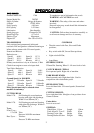
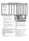
CHECK TYRE PRESSURE.
Check and maintain tyre pressure at 140 KPA (20 PSI) front
and 70 KPA (10 PSI) rear maximum
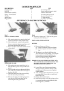
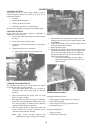
ADJUSTING THE SEAT
Tip the seat forward, loosen
the seat securing screws.
Relocate the seat for
operator comfort. Tighten
the seat securing screws and
lower the seat
Fig 5
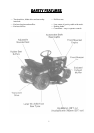
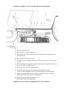
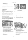
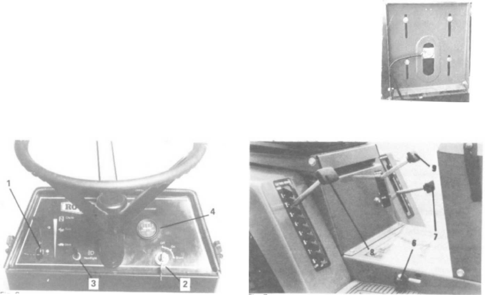
CONTROLS
Fig 6
1. Throttle control – Mounted on the dash panel and
connected to the engine carburetor controls. Has the
symbols for Slow, Fast and Choke.
2. Ignition Switch – This switch is part of the battery
ignition system and has three positions marked for Off,
On and Start. The switch is key operated and
automatically returns to the On position from Start
position when released.
3. Light Switch – On/Off toggle switch on dash panel for
actuating the headlights. Lights will not function when
engine is not running.
4. Amp Meter – Mounted in the dash panel it indicates the
battery charging current and discharge.
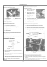
5. Brake/Clutch – Foot operated pedal on right side of
machine. Depressing the pedal disengages the drive belt
and engages Brake Disc .
6. Parking Brake – Hand operated knob right hand side.
Depressing the brake clutch foot pedal enables this knob
to be engaged and disengaged. Brake is locked on with
knob in up position.
7. Speed Selector –
Located on left of seat. In line selector
with speeds 1, 2, 3, 4 and 5 Down from Neutral and
Reverse through spring gate and up from Neutral.
8. Cutting Height Adjuster –
Located on right of seat with
low cut at bottom and high cut at top of setting.
9. Cutter Drive –
Lever located on left hand side of seat
mounting box. Down position disengages blade drive and
applies blade brake, Up position engages blades.
5