


CONTENTS
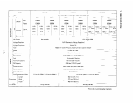
1. SPECIFICATIONS ..........................................
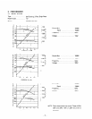
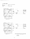
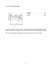
2. PERFORMANCE ...........................................
2-1 Model RGX180 ......................................
2-2 Model RGX240 ......................................
2-3 Model RGX240D .....................................
2-4 DC OUTPUT (RGX240, RGX240D) ........................
3. FEATURES ..............................................
4. GENERAL DESCRIPTION of GENERATOR ........................
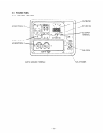
4- 1 External View of Generator ..............................
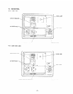
4-2 RGX180 Panel .......................................
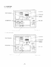
4-3 RGX240 Panel .......................................
4-4 RGX240D Panel. .....................................
5. CONSTRUCTION and FUNCTION ...............................
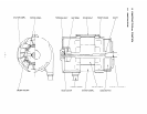
5- 1 Construction ........................................
5-2 Functions ..........................................
5-3 Description of Generator Operation .........................
5-4 Change of Engine Parts .................................
6. SAFETY PRECAUTIONS .....................................
7. RANGE of APPLICATIONS. ...................................
8. MEASURING PROCEDURE ...................................
9. CHECKING FUNCTIONAL MEMBERS. ...........................
9- 1 Stator Assembly ......................................
9- 2 Rotor Assembly ......................................
9- 3 Brushes. ...........................................
9-4 AVR (Automatic Voltage Regulator) ........................
9- 5 Fuse Holder and Circuit Breaker ...........................
9-6 Receptacle and AC Plug .................................
9- 7 Voltmeters and Pilot Lamp ...............................
9-8 Diode Stack Assembly ..................................
9-9 Primary Exciting Circuit ................................
10. DISASSEMBLY and REASSEMBLY ..............................
10- 1 Preparations and Suggestions .............................
10- 2 How to Disassemble ...................................
10- 3 How to Reassemble ....................................
10-4 Control Box Check, Disassembly, and Reassembly
...............
11. TROUBLE-SHOOTING .......................................
12.OPTIONS.. ..............................................
12-1 Caster .............................................
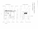
13. CIRCUIT DIAGRAM
........................................
Page
1
2
2
3
4
5
6
8
8
9
10
11
12
12
13
19
22
26
27
30
34
34
35
36
36
38
39
39
39
40
41
41
41
47
55
56
60
60
61