


ASSEMBLY
TURBO 96 01/11 Assembly Section 3-7
© 2011 Alamo Group Inc.
ASSEMBLY
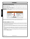
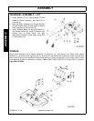
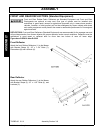
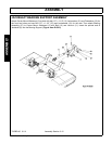
DRIVELINE CLAMP CONE YOKE
Loosen the yoke clamp cone with a 11/16” (17mm)
wrench and remove the cone from yoke. Slide yoke
onto the shaft and align hole for clamping cone with
annular groove of gearbox shaft. Reinstall cone and
tighten (75 lb-ft torque). Push and pull the driveline
to ensure it is securely attached to the shaft.
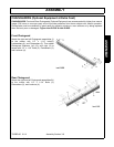
Regularly check the driveline yoke to ensure a tight
connection. To remove the yoke, remove the
connecting cone and pull yoke off the shaft. If the
cone cannot be easily removed by hand, drive it out
from the other side using a hammer and punch.
NOTE: The clamping cone is serviced only as a complete assembly. Do not attempt to disassemble the
clamping cone.
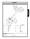
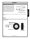
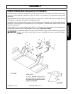
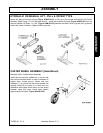
WHEELS
Install the Wheels on the Wheel Hubs. Note: If Laminated Tires are used, place the flat side of the Lug Nut
against the Wheel Note: the direction of travel and curvature of rubber segments in tire and install as shown in
FIGURE Asm-R-0127.