Operation Section 4-6
OPERATION
GK6072 08/01
© 2004 Alamo Group Inc.
OPERATION
1-9/16"1-9/16"
1-9/16"1-9/16"
1-9/16"
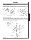
FIGURE 3FIGURE 3
FIGURE 3FIGURE 3
FIGURE 3
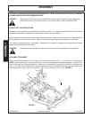
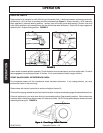
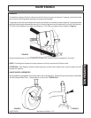
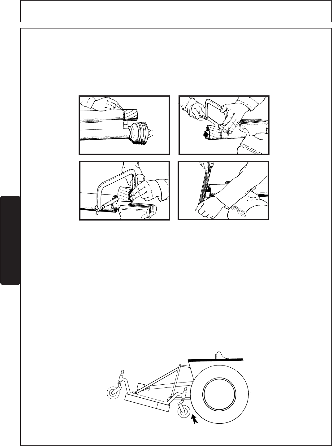
Figure 4 - Front Gauge Wheel ClearanceFigure 4 - Front Gauge Wheel Clearance
Figure 4 - Front Gauge Wheel ClearanceFigure 4 - Front Gauge Wheel Clearance
Figure 4 - Front Gauge Wheel Clearance
DRIVELINE LENGTH
Raise mower to full transport or until driveline just hits deck at front. If distance between colored tape and outer
shield tube is 1-9/16 or less, drive tubes should be shortened per Figure 4. Always maintain 1-9/16 clearance
when operated in shortest working position. shorten inner and outer guard tubes equally. Shorten inner and
outer sliding profiles by the same amount that the shield tubes were shortened. Round off all sharp edges and
remove burrs. Grease sliding profiles. FIGURE 3.
Lower mower to lowest position possible. Check distance from colored tape to end outer shield tube. Driveline
tube engagement must always exceed 12 inches. If not consult dealer to obtain longer driveline.
FRONT GAUGE WHEEL INTERFERENCE CHECK
Do not operate mower until this interference check has been performed. If you change tractors, you must
perform the check for that mounting.
Raise mower with tractor hydraulics to maximum height of tractor lift.
Pivot both front gauge wheels forward and check that there is clearance between gauge wheels and tractor tires.
If there is interference, you must move hitch pin to extended position (See assembly section). Move tractor tires
inward to obtain clearance or lower mower until clearance exists. Set 3-Point quadrant stop so mower cannot be
raised beyond set point. FIGURE 4.


