


MAINTENANCE
DB150 07/11 Maintenance Section 5-21
©2011 Alamo Group Inc.
MAINTENANCE
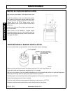
Assembly
Make sure all parts are clean and free of any contamination
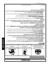
Install Bearing Cups (3 & 4) into Spindle Housing (2) using a suitable bearing driver to seat the cups. Caution
must be taken not to damage the cup or spindle housing, cups must be fully seated. If Cups are damaged
during installation or not fully seated, bearing and spindle assembly life are greatly reduced!
Never drive against bearing surface! Never used the mating bearing cone to seat the cup!
Once the Lower Cup is installed, the seal may be installed. The seal should be installed with the spring towards
the inside Press seal (7) into spindle housing, make sure seal is fully seated. Be careful not to damage seal!
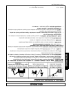
Press the Lower Cone (3) on the spindle shaft (1) use the proper tool when pressing the bearing onto the shaft,
driving against the inner race and not the rollers or cage. Any damage to the bearing will cause premature
failures of the bearing and spindle assembly.
Before installing the spindle (with the bearing pressed on it), lubricate the rubber portion of the seal. This will
reduce the chance of the Seal being torn by the installation of the spindle and is a necessary step when setting
the rolling Torque.
Turn the Spindle Housing Upside Down and insert the spindle (with the bearing pressed onto it) into the spindle
housing until the bearing cone contacts the cup in the Housing. During this step take care not to damage the
seal.
While supporting the Spindle and Housing turn the assembly over so that the assembly is setting on the
spindle.
Install the upper bearing (4) on the spindle shaft (1).
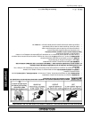
After the Upper Bearing is installed, install the nut (5) with the chamfer facing up. Run the nut down against the
bearing, but do not torque the nut at this time. Clamp the spindle Housing in a vise so that the spindle shaft can
rotate. Tighten the nut until the spindle shaft has a rolling torque of 25 in-lbs (that is it takes 25 in-lbs to rotate
the spindle shaft).
Install the tanged lockwasher (6) with the outside prongs facing upward.
Install the top nut (5) with the chamfer facing down. Block the spindle to keep it from rotating and torque the top
nut to a minimum of 100 ft.-lbs. Bend the tang of the lockwasher to fit into one of the grooves of the top nut.
Install vent plug (8) and Grease Fitting (9).
Fill spindle assembly with NLGI EP#2 Grease (Approx. 22 oz.)